


408-3194
2
of 3
Rev
K
2. Flex the wings of the cable while removing the
cable from the reel.
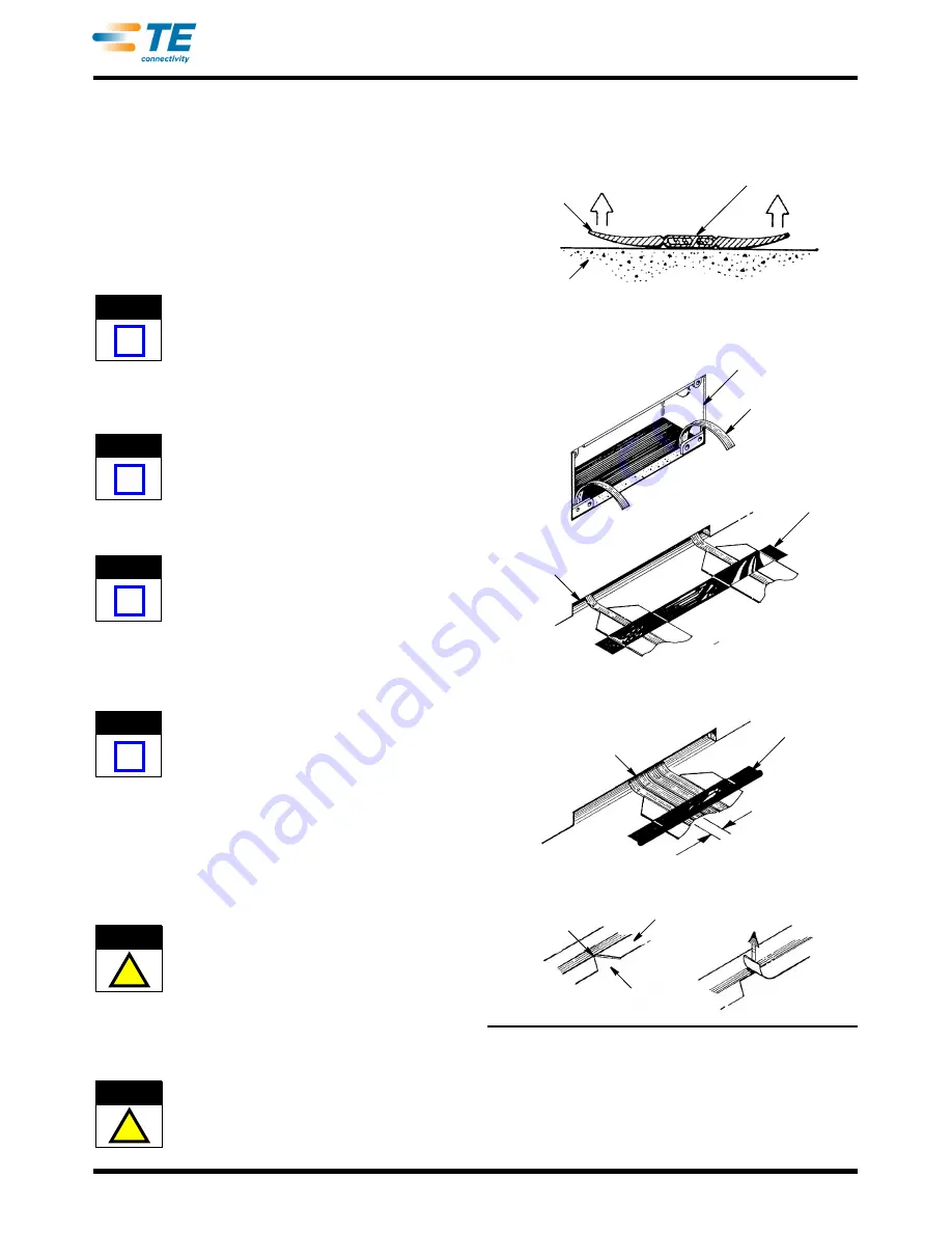
3. From the distribution point (wall box or floor
fitting), lay the cable on the floor with the printed
side of the cable facing up and the bow of the cable
pointing up. Refer to Figure 2, Detail A.
If more than two cable runs exit the distribution
point, remove the inner wing of each cable, then
place the cables side by side. See Figure 2,
Detail A.
To remove the inner wing, use Cable Notcher Tool
1725698-1 (available separately) to cut a notch to
the groove in the wing; then, flex the wing and tear
it back slowly. DO NOT cut into the center rib
containing the conductors. See Figure 2, Detail B.
4. Place hold-down tape over the cable area. See
Figure 2, Detail A.
Hold-Down Tape 553481-1 is available separately.
5. Cross-tape as required along the cable run.
Stretch the tape to remove any slack.
Spray Adhesive 553453-1 is available separately
and may be used to aid in adhering the tape to the
cable and floor surface.
6. If extra protection for the communications cable is
desired, install Floor Preparation 554123-[ ] and Top
Shield 553536-[ ] according to 408-3150; both are
available separately.
The communications cable does not require a top
shield or bottom shield; however, local inspection
requirements and certain floor finishes are
examples where extra protection for the cable
would be desirable.
7. If the cable requires directional changes, proceed
as follows:
a. Using Cable Notcher Tool 1725698-1, notch
the wings of the cable at 25.4-mm [1.0-in.]
intervals. Make sure to remove all notched
material. Refer to Figure 3, Detail A.
DO NOT cut into the center rib of the cable
containing the conductors.
b. Bend the cable to form a gradual turn. Refer
to Figure 3, Detail B for recommended length
and radius. Cover the turn with hold-down tape
to blend the profile of the cable at the notches.
DO NOT fold the cable. Cable must be notched and
cable bends must be gradual.
Figure 2
8. Terminate the cable to the transition block and
floor fitting outlet according to the instructions
included with the product.
NOTE
i
NOTE
i
NOTE
i
NOTE
i
!
CAUTION
!
CAUTION
Printed Side
of Cable
Bow of Cable
Floor
Detail B
Notch in Wall
Hold-Down
Tape (Ref)
Over Cable
Distribution
Point
1 or 2 Cable Runs
More Than 2 Cable Runs
Hold-Down
Tape (Ref)
Over Cable
7.92 mm [.312 in.]
(Typ) Centerline
to Centerline
of Cable
Detail A
Inner Wing
of Cable
Cut Notch
Tear Back
Groove
Inner Wing of
Cable Removed
(See Detail B)
Cable
Orienting Communications Cable
Laying Communications Cable


