background image

 3 

Section II: Installation and Operation

1.0 Installation 

1.1 General 

A.  To maintain the closure in proper working 

order, those making the shop or field 
installation must carefully follow the welding 
instructions and preventive maintenance 
instructions. 

B.  It is important to keep the following points in 

mind during installation: 

• 

Level the closure during the installation 
process; 

• 

Properly align the barrel collar; 

• 

Position the door hinge in the vertical 
position (horizontal on a vertical 
installation) to permit easy opening and 
closing of the door. 

C.  A bleeder valve and a pressure gauge must be 

installed on the vessel the closure is welded 
to. An operator must be able to bleed the 
vessel and determine when there is zero (0) 
psig within the vessel. 

1.2 Welding Procedures 

A.  The same welding procedures are to be used 

whether post-weld heat treatment is required 
or not. 

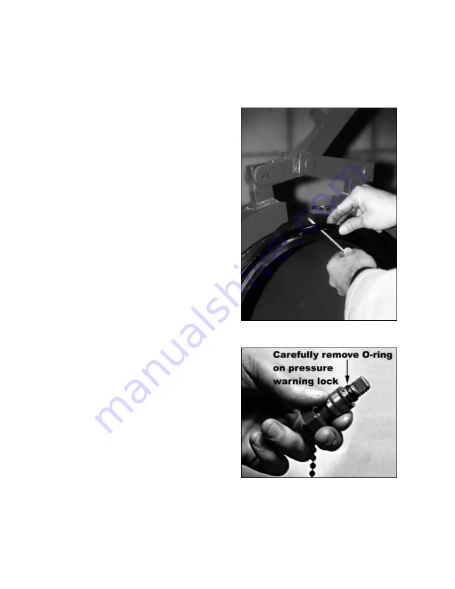
1.  Remove closure door O-ring and pressure 

warning lock O-ring before welding. (See 
Figures 2 and 3.)  

2.  If post-weld heat treatment is required, it is 

recommended that it be accomplished by 
localized stress relieving. If that is not 
possible, the closure door must be 
removed prior to heat treatment. (See 
Section II, subsection 3.1, beginning on 
page 9, for removal instructions.) 


Figure 2. Remove O-Ring on Closure Door 


Figure 3. O-Ring on Pressure Warning Lock 

Summary of Contents for D2000

Page 1: ...TDW Pub No 00 3795 0283 March 2002 TDW D TDW D TDW D TDW D 2000 2000 2000 2000 Closure Closure Closure Closure Installation Operation and Maintenance Instructions 16 30 Inch...

Page 2: ...es under pressure The purchaser of this equipment is responsible for the manner in which this equipment is used and maintained and for the training and competence of the operators Should any difficult...

Page 3: ...pose 1 2 0 Discussion 1 3 0 Safety 1 Section II Installation and Operation 3 1 0 Installation 3 2 0 Operation 5 3 0 Removal and Installation of Closure Door 9 Section III Maintenance 11 1 0 Maintenanc...

Page 4: ...ii...

Page 5: ...sure 3 0 Safety 3 1 General TDW clamp ring closures are designed for fast easy and safe operation A closure may not operate effectively if it has been subjected to misuse or external damage or has bee...

Page 6: ...ce is not parallel to and concentric with the barrel collar face contact the TDW factory for assistance and repair as necessary Do not allow anyone to operate a TDW closure who is not fully trained in...

Page 7: ...valve and a pressure gauge must be installed on the vessel the closure is welded to An operator must be able to bleed the vessel and determine when there is zero 0 psig within the vessel 1 2 Welding P...

Page 8: ...four inches around circumference and check again for proper alignment CAUTION When welding on the barrel collar a low welding heat range and the following proper sequence of welds will help prevent p...

Page 9: ...concerns personal safety precautions and must be observed to prevent injury to personnel Always keep this plate legible Figure 6 Warning Plate B The closure contains a pressure warning lock to alert t...

Page 10: ...ing check lubrication of all hinge points on the clamp ring assembly These include the following One clamp ring pivot pin Figure 9 Three clamp ring link pins Figures 9 and 10 these pins should be lubr...

Page 11: ...posite the door hinge Do not stand in front of closure or on door hinge side of closure or above it in a vertical installation while opening Spraying line fluids or sudden door opening may result in p...

Page 12: ...es Do not force the clamp ring handle if the clamp ring will not close freely Verify that the door is adjusted properly and check for debris NOTE As the clamp ring is closed the bars attached to the b...

Page 13: ...ring J Open the door clear of the clamp ring assembly K Lift the door until the lower hinge pin clears the lower hinge bracket Pull the lower hinge pin away from the bracket and remove the lower bear...

Page 14: ......

Page 15: ...t for cuts and scratches or deterioration Replace O rings if there is any sign of damage Figure 17 Lube O Ring on Pressure Warning Lock Screw Figure 18 Additional Lube Points 1 3 Clamp Ring Always cle...

Page 16: ...12 C Keep the assembly free of paint D Lube inside the bushing periodically Figure 19 Lube Bushing for Pressure Warning Lock...

Page 17: ...ressure warning plate 18 1 pressure warning plate 19 2 clamp ring locking lug 20 1 Spirol pin 21 2 flat washer 22 2 cotter pin 23 8 setscrew 24 8 cap plug 25 2 flat bar 27 1 handle 28 2 rubber seal 29...

Page 18: ...14 Figure 20 D 2000 Clamp Ring Closure 16 30...

Page 19: ...ducts or parts must be held for inspection by TDW or at TDW s option returned to TDW s factory Customer shall prepay shipping charges and shall pay all duties and taxes as applicable for products or p...

Page 20: ...illiamson Inc is ISO 9001 certified TDW Pub 00 3795 0283 March 2002 Copyright 2002 Printed in USA All rights reserved Visit TDW s home page on the World Wide Web at www tdwilliamson com T D Williamson...

Reviews: