AN-000327
Page 5 of 11
Document Number: AN-000327
Revision: 1.0
Host Computer Setup
SmartSound One comes pre-programmed to allow for plug-and-play functionality out of the box. It is first recommended to supply
power to the board with a micro USB cable and verify the blinking LED (reference designator DS5) to ensure successful boot. After
plugging into a host like a PC, the board will be recognized as an audio card for recording in any audio recording software such as
Audacity, which is a free to use and can be downloaded here
https://www.audacityteam.org/
. In order to enable this capability, the
user must perform a one-time configuration of the sound card settings in Windows detailed below.
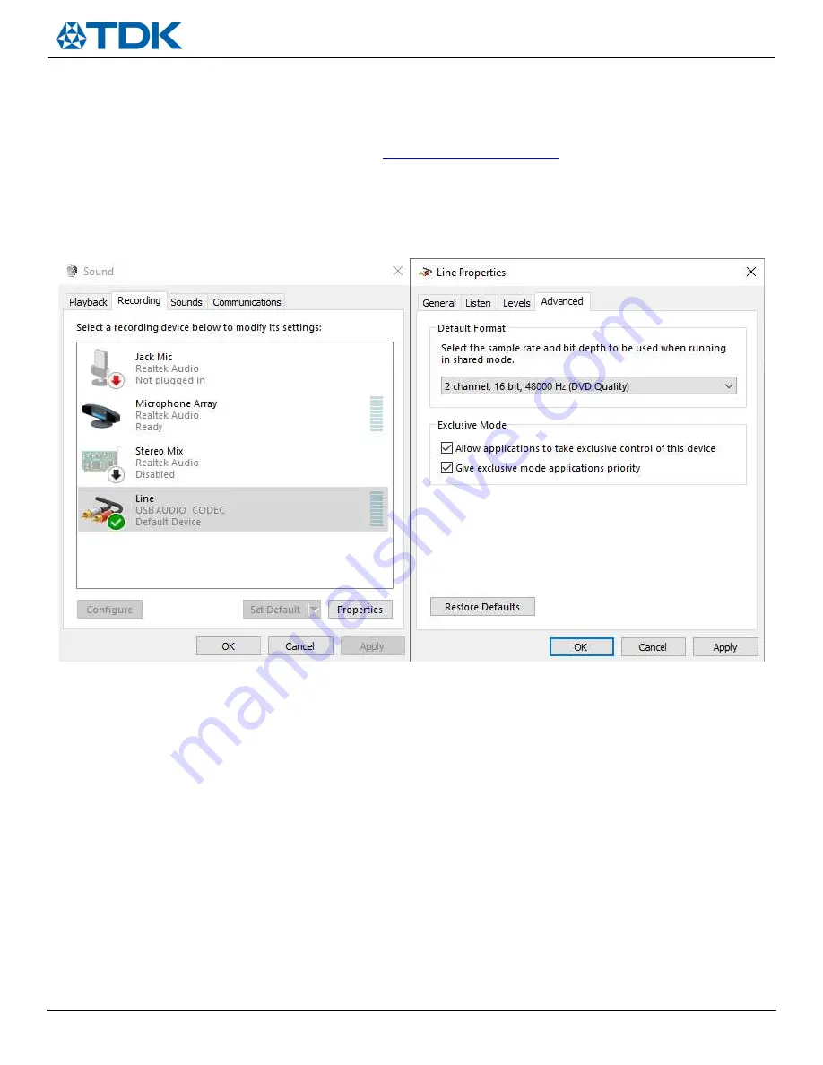
1)
Go to Sound Device Manager (Control Panel -> Hardware and Sound -> Sound)
2)
Right click on the ‘USB AUDIO CODEC’ device
3)
Under the ‘Advanced’ tab, select 2 channel, 16 bit, 48000 Hz (DVD Quality) and hit ‘Apply’, shown in
Figure 5
Figure 5.
Windows Sound Settings
To verify that this was configured properly:
1)
Without any microphone FPCBs attached to the SmartSound Board, open Audacity
2)
Configure the input device as the ‘LINE IN USB AUDIO CODEC’ and the output device to user’s preference (i.e speakers or
headphones)
3)
Hit record with SmartSound One in standby mode (DS5 LED blinking), and user should see
a.
-40dB 400Hz sine tone on the Left channel
b.
-40dB 200Hz sine wave on the Right channel
The user can populate the MIC_BOOST jumper to apply +30dB gain which results in a -10dB test tone level. Reference
Figure 1
,
jumper J7 or the “
Configuration Header Settings
” section for the MIC_BOOST jumper location. See
Figure 6
as a reference for these
standby mode waveforms.
Once the test tone has been verified in standby mode, the user may proceed to select the microphone interface mode of interest
and plug the included FPCBs to start recording.


