background image

R

2800 LAURA LANE • MIDDLETON, WI 53562 • (800) 288-9383 • FAX (608) 836-9044 • www.tcsbasys.com

6

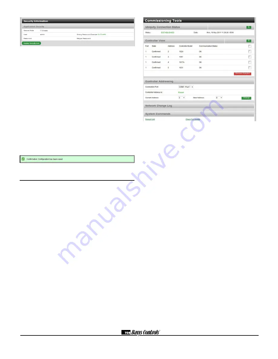
SECURITY INFORMATION

This section contains settings which control the security 

of the gateway within the QD2010a and whether or not 

it can be accessed by directly connecting to it. Enabling 

Secure Mode disables all web interfaces INCLUDING 

THE SETUP PAGE and requires a specially configured 

USB flash drive or TCS Technical Support access to 

the QD2010a unit if it is online with Ubiquity central 

server to "unlock" it. Typically, this Secure Mode is 

left unchecked (disabled). You also have the option to 

change the default login credentials used to access the 

Setup Page. Changing this to something other than the 

default requires a specially configured USB flash drive or 

TCS Technical Support access to the QD2010a unit if it 

is online with the Ubiquity Central Server to reset it back 

to the default password. Typically, this password is left at 

the default (see Initial Configuration section for details). 

Once you are finished entering information in this section, 

click the Update Security Info button.

Commissioning Tools               

A separate page which contains various commissioning 

tools can be accessed by clicking the "Commissioning 

Tools" button at the bottom of the Setup page. This 

page gives you access to additional information about 

the connection status of the QD2010a and the controller 

network connected to it. This page is mainly designed 

to be used while the unit is in setup mode. However, in 

some cases you may be directed to access it once the 

unit is communicating with the central server. In that 

case, TCS Basys Controls technical support staff will 

instruct you on how to access this page.

UBIQUITY CONNECTION STATUS

This section displays the status of the connection 

between the QD2010a and the central server. You have 

3 options for the message that will appear her:
1) Error - No Route to Host -- this means the unit does 

not currently have an Ethernet connection. You will also 

see this message when the unit is in Setup mode.
2) Connected -- this means the unit is able to talk to the 

Ubiquity central server BUT is not being matched up 

with a specific Site Home page. This will be the case 

until one of our staff has linked the QD2010a to its 

webpage.
3) Established -- this means the unit is able to talk to 

the Ubiquity central server AND it has been matched 

up with its Site Home page. All Ubiquity functions 

(monitoring, programming, alarming, etc.) should be 

available through the user interface at this point.
Clicking the green button with the arrow on it on the 

right side of the Ubiquity Connection Status title bar will 

refresh the connection status.


CONTROLLER VIEW

This section allows you to see what controllers have 

been found by the QD2010a and view each controller's 

address, model, and communication status. The state 

field will show AUTO-DETECTED initially when found 

by the unit and CONFIRMED once the controller has 

been recognized by the Ubiquity central server. This 

information allows the installer to verify that each 

controller has been found by the QD2010a and is 

communicating with the local network.
Clicking the green button with the arrow on it on the 

right side of the Controller View title bar will refresh each 

controller's status.

Summary of Contents for QD2010a

Page 1: ...mory Integrated 10 100 Ethernet controller with firewall capabilities Interface into Ubiquity Interface for configurations Remotely upgradable firmware User definable communication cycles SSL Secure Socket Layer enabled web pages Integrated controller addressing Supports up to 3 TCS Basys Controls devices Contents Description 1 Features 1 Material List 1 Programming 2 Prior Connection to Network 2...

Page 2: ...n of the QD2010a by simply connecting it to a laptop or desktop PC Caution The QD2010a comes programmed with a default setup mode and functions as a DHCP server When setting up the unit be sure it is not connected to another DHCP enabled network Components diagram casing removed Not used Initial Configuration Before connecting the QD2010a to a LAN or WAN you must first configure the unit for opera...

Page 3: ...if you do not or you are unsure connect to a UPS PK3100 To connect the QD2010a to a LAN Ethernet connect an Ethernet cable not included to the RJ 45 connection on the side of the unit Connect the other end to the LAN network hub Power adapter QD1010 USB To RS485 Control Network SIDE A SIDE C SIDE D LAN Ethernet HDMI if applicable USB VGA output if applicable 5V Power ETHERNET HUB Crossover Cable s...

Page 4: ... 5 V If you measure across A and B you should get 0 VAC and 1 to 4 VDC There should be 0 VAC and 0 VDC between either A on B and the shield If you are getting more than this check for runs against high voltage for exposed wires to see if grounding at only one side or that you have used dedicated power for the controllers or if you have reversed power on a Controller s NOTE By using wire cable cons...

Page 5: ...and the drop down menu will be left at Disabled If a proxy is required you can select the correct type from the drop down and then enter all the related details in the fields that appear Once you are finished entering information in this section click the Update Commissioning Info button Unlike the other section updating this section may cause the unit to reboot automatically within 5 minutes of c...

Page 6: ...ccess it once the unit is communicating with the central server In that case TCS Basys Controls technical support staff will instruct you on how to access this page UBIQUITY CONNECTION STATUS This section displays the status of the connection between the QD2010a and the central server You have 3 options for the message that will appear her 1 Error No Route to Host this means the unit does not curr...

Page 7: ...cted if this method is being used You will also need to reconfigure the COM port when finished NOTE When using this second method for changing addresses ALL controllers connected to that COM port will be given the same address So there must only be ONE controller connected to the network NETWORK CHANGE LOG In this subsection you will be able to view all address changes performed using the QD2010a ...

Page 8: ...010a 2 Apply power 3 If the QD2010a has not been pre programmed it can be programmed at this time 4 The unit is now ready for operation TROUBLESHOOTING No Communications with Controllers on the network Make sure the baud rate selection for the QD2010a is set to match the baud rate of all the controllers on each port network All controllers on the network must have a unique address excluding the ad...

Reviews: