DGND
DGND
DGND
DGND
DGND
DGND
DGND
DGND
DGND
DGND
DGND
DGND
DGND
DGND
DGND
DGND
DGND
DGND
DGND
DGND
DGND
DGND
DGND
DGND
DGND
DGND
DGND
DGND
NC
PANEL_VCC
PANEL_VCC
GND
GND
NC
3
2
1
4
5
6
7
8
9
10
11
12
13
14
15
16
17
18
19
20
21
22
23
24
25
26
27
28
29
30
31
32
33
34
35
36
37
38
39
40
41
42
43
44
45
46
47
48
49
50
51
GND
LD_EN
GND
GND
3D_EN
GND
LVDS_SEL
3D_TEMP1
NC
3D_LR_OUT
DIM/3D_TEMP0
SCL
PANEL_VCC
SDA/WP/SCL
3D_VSYNC_IN
3D_FORMAT1
3D_FORMAT0/SDA
NC
PANEL_VCC
GND
GND
RXO0+
RXO1-
RXO1+
RXO2-
RXO2+
RXOC-
RXOC+
RXO3-
RXO3+
RXO4-
RXO4+
RXE0-
RXE0+
RXE1-
RXE1+
RXE2-
RXE2+
RXEC-
RXEC+
RXE3-
RXE3+
RXE4-
RXE4+
RXO0-
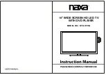
FHD FFC LVDS
46-FFC14W-51SG
NC
NC
PANEL_VCC
PANEL_VCC
GND
GND
GND
NC
NC
3
2
1
4
5
6
7
8
9
10
11
12
13
14
15
16
17
18
19
20
21
22
23
24
25
26
27
28
29
30
GND
NC
GND
RXE3+
GND
RXE3-
RXEC+
RXEC-
GND
RXE2+
RXE2-
RXE1+
RXE1-
GND
RXE0+
RXE0-
LVDS-SEL
GND
PANEL_VCC
PANEL_VCC
NC
HD FFC LVDS
46-FFC03W-30SG
GAIN
GAIN0
20dB
26dB
32dB
36dB
L
H
H
H
L
H
L
GAIN1
close to SOC
L
R+
R-
L-
L+
MUTE Circuit
close to SOC
Standby=L
Normal=H
HI =>Panel ON
NORMAL POWER 3.3V
STANDBY POWER_3.3
DDR3 POWER
core power
If 12v<8.3V then reset_H
If 24v<17.8V then reset_H
Power AMP TPA3113D2
Close to SOC
3) R967 IS PANEL SPECS SELECT 0R or NC,DEFAULT IS 0R TO GND.
LO =>Panel OFF
LVDS-SEL DEFAULT IS 0R TO GND
NOTE:1) 10 Bit PANEL:R907/R908/R9909/R910 IS 0R
2) 8 Bit PANEL:R907/R908/R9909/R910 IS NC
TXE3-
TXE0-
TXE1-
TXE1+
15
16
17
18
19
20
21
22
23
24
25
26
27
28
29
30
31
32
33
34
35
36
37
38
39
40
41
42
43
44
45
46
47
48
49
50
51
P912A
U600
TPA3113D2
R606
12V
L600
L201
600R
C348
R231
C241
C240
C503
R232
0.1U
33K
R969
0BAV99
Q901
R241
56K
R242
PANEL_VCC
C238
NC/1M
C349
C600
NC
C604
1000P
0R
C612
R611
R613
10K
C625
1000P
C610
1000P
L603
L601
R629
100K
C609
1000P
100R
10K
R610
L607
L605
C618
R604
R609
15
16
17
18
19
20
21
22
23
24
25
26
27
28
29
P912B
Z-PANEL_VCC
TXO3-
TXO1-
TXO1+