Confidential
TMPA8873PSNG /CMNG /CPNG /CRNG /CSNG
2005/03/29
35
6. AV
Switch
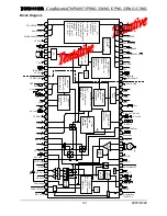
The audio switch has two inputs for an external audio, and one for internal demodulated audio signal. The
two external audio inputs can use as audio stereo input. The switched audio signal goes into the audio
attenuator, which has controllability of audio gain from 0dB to –80dB or less with near log curve
characteristic.
The video switch has one input for an external CVBS or S-VHS signal, the other for the demodulated TV
video signal and the last for an external YCbCr signal, mainly coming form a DVD player. The CIN terminal
for the external S-VHS signal has capability to detect DC level of the input signal, and the micro controller
can read the result as ‘CIN DC’ through the IIC bus. This function may prepare a way for automatic switching,
when inserting S-VHS connection, by means of software control.
A monitor output is available with the selected video signal. In the case of selecting S-VHS input, Y and C
signals are mixed for the monitor output. This output is useful for signal detecting by the TC3 counting of the
micro controller through an external LPF circuit for strict signal detecting performance.
7. Asymmetric
Sharpness
External analog circuits are likely to generate ‘over-shoot’ signal. The asymmetric sharpness circuit is
provided to compensate this undesired signal. It is possible to get more gain of pre-shoot than over-shoot by
using the asymmetric sharpness, instead of that a conventional sharpness function generates both pre-shoot
and over-shoot symmetrically.
8. Scan Velocity Modulation (SVM)
The SVM output is available for a large screen size TV. The SVM or the monitor output is selectable at pin
45 through the IIC bus. The SVM gain and timing is also selectable to match an external SVM drive circuit.
9. Chroma
Demodulator
The PAL/NTSC chroma demodulator is integrated with the automatic color system detection. The 1 H-delay
line is integrated on the chip for PAL chroma demodulation. The 1 H-delay line can acts as a chroma comb
filter on NTSC chroma system.
10. Base Band Color System
TMPA8873 features a base band color system for a YCbCr inputs capability for a DVD and a SDTV signals.
Those signals are demodulated out side of TMPA8873, so that color signals (Cb, Cr) has different color level,
different demodulation angle and different relative amplitude from the color signals demodulated by the
internal chroma demodulator of TMPA8873. The base band color system is required to have control functions
of color saturation, TINT and relative amplitude, and TMPA8873 has all of these functions in it. Because of
base band TINT function, TMPA8873 has capability to control PAL TINT, which is basically hard to control on
a conventional signal processor IC. Of course the control software can inhibit the PAL TINT function.
11. Transparent OSD Interface
TMPA8873 provides a transparent OSD capability. A conventional OSD system provides a half-tone
function for OSD interface, by reducing the gain of a main picture signal during high period of ‘Ym’ signal
from the micro controller. TMPA8873 has one more control line as ‘I’ for OSD from the micro controller, which
enables to put a color on the same area of half-tone, so that software can achieve a see-through color menu by
using the transparent OSD.
12. Noise Level Detection
The Noise detector is integrated. The noise detection level is set by WRITE BUS register. The result can be
read through the IIC bus. According to the result, the micro controller can adjust level of some controls in the
signal processor. For example,
(1)
When a noisy signal comes in, horizontal synchronization is influenced and the picture on the screen
looks bad. Selecting less H-AFC gain makes the picture looks better.
(2)
When a very noisy signal comes in, the vertical frequency detector sometimes makes miss-detection, and
causes vertical jittering. Selecting the auto-50 Hz mode or auto-60 Hz mode, according to the vertical
frequency information just before, may solves the vertical jittering.
Summary of Contents for 21M62S
Page 1: ...SERVICE MANUAL MODEL 21M62S CHASSIS M123SP...
Page 20: ......
Page 37: ...6 PCB Layout...
Page 38: ......

