______________________________________________________________________________________________________________________________________________________________________________
__________________
TC Electronic A/S
Gold Channel Service manual
page 7
Built-in Test Program
The Gold Channel has a Built-in Test Program. To run the program; Press the PROGRAM button while powering on. Select RUN TEST PROGRAM and press ENTER. Follow the
instructions on the display. To leave the Built -in Test Program; turn off the power.
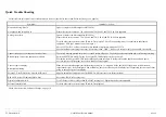
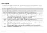
Gold Channel Built-in-Test Program v3.09 has following tests:
TEST
Function / Comments
Keys
Tests the keys at the front panel one by one. If a key hasn't been pushed a warning message will appear when leaving the test
IN knobs
Tests the function of the Input potentiometers
PARAM+VALUE
Tests the steps of the encoders. Each step is counted at the display, if not; check soldering at the encoder ot the front connector.
LED's
Tests the LED's at the front panel one by one. If no light; check soldering at the LED and at the flat cables between the front boards.
Display
Tests all dots in the display. If any missing; replace the display. If the backlight is bad or blinking; check the soldering on the display itself, especially the two
connections going to the upper of the display.
Analog I/O
A sine wave is generated on both analog outputs. When connected to one of the analog inputs the display reads OK if the level is correct. In this way a
problem might be narrowed down to a specific input or output. The levels can be checked at 60dB, 40dB, 20dB and 0dB PAD.
Note: On the display it says "Meter must show -12dB.." However, if the meter only shows -16dB, it is also OK.
Note: In case of defective IC35, IC36, IC41 they should be replaced with type MC33079
Digital I/O
A digital signal is generated on the digital output. When connected to the digital input the display reads OK if the level is correct.
Midi I/O
A midi signal is generated on output. When connected to the input the display reads OK if the signal is correct. The midi signal from input is sent on to MIDI
THRU. If not OK; try with another midi cable or check soldering and components in the midi circuit.
Pedal socket
Tests the status on the EXTERNAL CONTROL IN. When no jack plug is inserted the result must read "Not OK". If a jack plug is inserted and the tip of the
plug is connected to ground, the result must read OK.
PCMCIA
Tests whether programming, reading or deleting are OK. NOTE: All data on PCMCIA card will be destroyed.
Battery
Tests the DC voltage at the Back up battery. If low; check battery voltage with a multimeter and check also the standby current by measuring the voltage
across R27; max. 20mV (numerical value). If the voltage is higher; replace IC4. When replacing battery, please refer to section "exchange of battery"
System.
Tests the MPU, DSP, DARC, SOUND RAM to some extent.
Summary of Contents for Gold Channel
Page 1: ......


