background image

WHERE GREAT RECORDINGS BEGIN

42

by Loren Alldrin

Have you ever thought about where recordings really begin? If this question brings to mind a
tape deck, mixer or analog-to-digital converter, you're a bit too far down the signal path. While
these components are crucial parts of many recording chains, they're not where the process
actually beings. Instead, it's the microphone that's the real starting point for most recordings.

The microphone is responsible for the crucial first conversion that turns minute changes in air pressure (sound)
into an electrical signal. How well the mic performs this task has a profound effect on the quality of the
recording. Capture a brilliant performance with a bad mic (or poor mic placement), and the result is a bad
recording. Place the right mic in front of a talented instrumentalist or vocalist, and you'll consistently capture
excellent recordings.
Choosing and using microphones well involves a unique mix of artistry and technical savvy, making it one of
the more enjoyable - and challenging - aspects of recording. In the next few pages, we'll help you achieve great
recordings by covering some key principles of microphone technology, selection and placement.

Microphones: The Inside Story

Microphones use three main methods to convert sound to electricity, a distinction that divides mics into the
dynamic, ribbon and condenser classes. The dynamic mic is simplest of the three, and works much like a
loudspeaker in reverse. As sound vibrates a thin, round diaphragm, a coil of wire moves back and forth through
a magnetic field to generate a changing voltage. This voltage is the microphone signal. In a ribbon mic (which
is closely related to the dynamic mic), the ultra-thin wisp of metal that makes up the ribbon sits directly in a
magnetic field. When it moves in response to sound, the ribbon generates a corresponding voltage that is the
mic's output signal.

Condenser mics suspend an ultra-thin membrane above a stationary, electrically charged backplate. Thanks to
the electrical principle of capacitance, any movement of the diaphragm causes a small change in voltage. This
tiny signal is then amplified inside the mic body to become the mic signal. Because condenser mics have on-
board amplifiers, they require a source of power. The most common way to power condenser mics is with
phantom power, a voltage sent down a standard mic cable by a preamplifier or mixer. It's important to note that
applying phantom power to a ribbon mic will often destroy the ribbon, and likewise may harm some dynamic
mics.

The condenser mic class splits further, based on the size of the diaphragm used to pick up sound. Small-
diaphragm condenser mics use diaphragms less than 1/2-inch in diameter. Large-diaphragm condensers
frequently boast diaphragms an inch or more in diameter. Diaphragm size affects many aspects of mic
performance, including frequency response, directivity, sensitivity and overall sonic character.

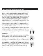
Finally, mics differ in their pickup patterns--this describes how a microphone responds to sound coming from
all sides (see figure 1). If a mic picks up all sounds equally, it's a non-directional or "omnidirectional" design.
More common are mics most sensitive to sounds coming from a heart-shaped area directly in front of them,
which describes the "cardioid" pattern. Other patterns include bi-directional (most sensitive to sounds coming
from directly in front and behind), supercardioid and hypercardioid. The latter two are more-directional
versions of the standard cardioid.

Summary of Contents for Gold Channel

Page 1: ...USERS MANUAL Gold Channel DIGITALLY ENHANCED MIC PREAMP...

Page 2: ......

Page 3: ...d other functions Inputs Outputs General description to get started Selecting the primary Inputs Outputs Clock Dither and Insert Setting the Analog Input Gain Digital In Master Out and Analog Out leve...

Page 4: ...ncies that are inherent in ribbon microphones As the industry started moving forward with condensers those consoles with their pre eq provided the seminal sounds that we grew up on The mixers now had...

Page 5: ...ng in full three dimensional stereo and color I am at their feet Bruce Botnick June 1998 Bruce Botnick is a recording engineer and producer whose work spans the last three decades Although he is prima...

Page 6: ...ors set a whole new standard for what you can expect from a stand alone mic preamp The Gold Channel is equipped with 24 bit AD DA converters AES EBU S PDIF and ADAT Toslink Optical Inputs and Outputs...

Page 7: ...ouble sample rate 88 2 or 96 kHz Gold Channel features Two channels of high end mic preamplification Two types of Expander Gate algorithms that enable you to use either an over easy Noise Gate or a mo...

Page 8: ...40 dB LED s is ON Note Set PAD range in the Utility display to get access to 60 dB PAD 48V on off Supplying 48V Phantom power to condenser microphones Phase Inverts the phase of the input signal by 18...

Page 9: ...when the Gold Channel needs you to confirm The Exit key is normally used to exit a menu or to cancel an action FUNCTIONS The four Function buttons give access to the primary display groups Programs H...

Page 10: ...s Hot on all XLR s IEC and AES standards You must use balanced XLR XLR cables to get the 48V phantom power to your condenser microphones External control jack works with the optional TC Master Fader t...

Page 11: ...THE SIGNAL FLOW 11 On this page you can see the signal flow through the Gold Channel presented in a technical drawing...

Page 12: ...an analog device like a tube compressor Select Line as Insert send return on the Signal page and set the Insert block position to either Pre or Post processing on the Layout page Make sure that the D...

Page 13: ...of the block you want to edit or dial the Parameter wheel to place the cursor on the block you want to Edit and press Enter Press the Exit key when you want to return to the Edit display or double cli...

Page 14: ...ing if no clock is present or if the Gold Channel cannot lock to the incoming clock S PDIF Digital S PDIF can use up to 20 bits Use the RCA jacks In Out for this connection S PDIF should use unbalance...

Page 15: ...ct Input source For instance you select AES EBU as your input source the Gold Channel now automatically switches the Clock parameter to Digital NOTE The external sync input will only recognize standar...

Page 16: ...switch to Line inputs and run the Auto Gain Set again Select Selects what channel s you are working with Ch 1 Ch 2 Ch 1 and Ch 2 or Stereo The difference between Ch 1 Ch 2 and Stereo is that in the f...

Page 17: ...nnels Digital input levels These parameters control the digital input if you have selected it on one or both channels If you are not using a Digital input the bars will be grayed out and you have no a...

Page 18: ...etween the Factory User and Card banks Factory presets is marked F User presets is marked U and Card presets is marked C Partial Recall The grid at the left of the display is used to make what we call...

Page 19: ...from the List display you will always get a normal Recall of the preset not a Total or Partial Recall Exercise 1 How to Recall a preset In this Exercise we are going to recall a couple of presets Pre...

Page 20: ...User preset entering the Store display will take you to the original User preset space You can then press ENTER to overwrite the old User preset or you can select another User or Card bank position m...

Page 21: ...nd use the menu keys to access the Store display Dial the Value wheel to select a storage space Dial the Parameter wheel to go to the Name line Dial the Value wheel to scroll through the Letterbox Pre...

Page 22: ...s Only limited by available Grid positions Basic operation is accomplished by using the Parameter wheel to change cursor position between the various block positions and the Value wheel to change betw...

Page 23: ...44 1 48 kHz Mode in a serial way for channel one s input NOTE The signal for Ch 2 will be taken right after Locut and Softclip but before Phase Invert Therefore Locut and Softclip will be set to Off o...

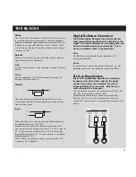
Page 24: ...on M S recording technique in this manual NOTE This M S matrix runs simultaneously with the M S matrix in the output block Unit With this parameter you can change the unit that the delay time is measu...

Page 25: ...cessing blocks and contains parameters to handle send return signals and direct channel one and two signals The idea of the extended Insert block is to enable a normal send return insert but also to t...

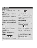
Page 26: ...meter you can decide the maximum number of dB the gate shall attenuate See the graphics to get a better understanding SIDECHAIN The Sidechain is the reference signal that the Gate is listening to inte...

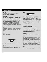
Page 27: ...tio at 2 1 means that for every 2 dB the signal exceeds the threshold only 1dB comes out Compressor Hold Is the time that the Expander Gate will keep the Ratio at 1 1 below the threshold before the Re...

Page 28: ...The Sidechain is the reference signal that the Compressor is listening to internally for processing You will never hear this signal on the output Input When placed on Channel 1 you can select the Side...

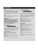
Page 29: ...tion Lo Shelving filter with 18 dB gain and four fixed frequencies Mid Bell filter with 18 dB gain and five fixed frequencies Hi Shelving filter with 18 dB gain and fixed frequency at 2 5 KHz Hi Cut C...

Page 30: ...efore well suited for limiting the maximum level in a specified frequency range e g the bass Ratio The Ratio of the gain reduction When the Ratio is set to 4 1 it means that for every 4 dB the defined...

Page 31: ...e all the blocks on Ch 2 for processing the sidechain signal on Ch 1 You can also have a completely different input on Ch 2 NOTE When two blocks are linked you cannot select Ch 2 as input for Ch 1 Sid...

Page 32: ...Protect Sets the Preset Protect function On Off Protect Low limit Sets the lower limit of the preset protect The current number is included in the protection Protect High limit Sets the higher limit o...

Page 33: ...t to ROM Factory USER CARD or Custom This means that you can guide all incoming Program changes to any of the three banks or you can design your own Custom MIDI map Custom Map In the Custom Map you ca...

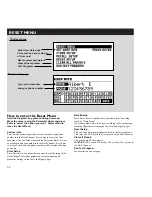
Page 34: ...er into the Gold Channel Press Enter to accept Your name and phone number will be displayed during power up Store Setup Press Enter twice to confirm that you want to save the setup of the Gold Channel...

Page 35: ...Connect ADAT output to ADAT input PPM must show 0 DB to pass test Press Exit to leave Digital I O test Midi I O test Select Midi I O test by pressing Enter Connect Midi Out to Midi In Prg change 1 128...

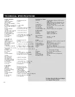
Page 36: ...20 40 60 20 Hz to 20 kHz 0 0 3 dBFS 66 dB 20 Hz to 20 kHz 82 db 20 Hz to 20 kHz 60 dB 50 60 Hz 70 dB 1 kHz 24 bit 1 bit 128 times oversampling 0 8 ms 48 kHz XLR balanced pin 2 hot 50 Ohm active transf...

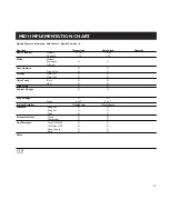
Page 37: ...Messages X X Altered Note Number X X True Voice X X Velocity Note ON X X Note OFF X X After Touch Key s X X Ch s X X Pitch Bend X X Control Change X X Prog Change O O True 0 127 0 127 System Exclusive...

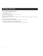
Page 38: ...using Analog input but the input selected is Digital or some send return has been selected on the Signal page without anything connected You do not hear what you expect as Ch 2 input Ch 2 gets it inpu...

Page 39: ...ed and used in accordance with the instructions may cause harmful interference to radio communications However there is no guarantee that interference will not occur in a particular installation If th...

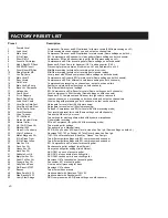
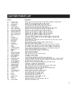
Page 40: ...ale vocals Same settings on both channels Compressor and EQ for different vocals same settings on both channels Comprehensive processing on channel one output on channel two Another vocal preset Same...

Page 41: ...ssor EQ and expander for floor tom Same settings on both channels Compressor for cymbals Two compressors on channel one output on channel two for heavy comp of drums EQ and comp for chimes Comp and EQ...

Page 42: ...is closely related to the dynamic mic the ultra thin wisp of metal that makes up the ribbon sits directly in a magnetic field When it moves in response to sound the ribbon generates a corresponding v...

Page 43: ...r designs are generally much sturdier than ribbon mics but still aren t as tough as most dynamics Sonically condenser mics tend to have the most open accurate sound with the most extended high frequen...

Page 44: ...t miking distances of eight inches to three feet are most common Apart from miking distance the orientation of mic to instrument or voice can have a significant impact on the sound Since high and low...

Page 45: ...hannel offers a wealth of power to amplify and process microphone signals This power can be used to further enhance a great sounding mic signal or it can be used to correct a not so great sound Your j...

Reviews: