Operating Instructions
8
7
OperaTIng InsTrucTIons
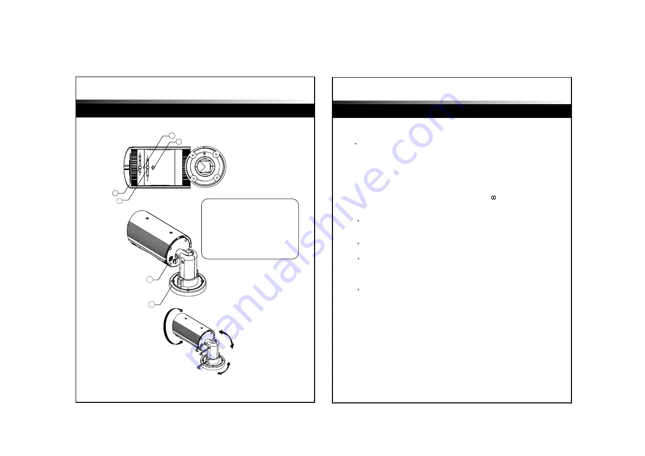
Name of each part
Installation
T W
N
H
DC LEVEL
L
1
3
2
4
5
6
1. ZOOM LEVER
2. FOCUS LEVER
3. FOCUS / ZOOM BOLT SCREW
4. DC LEVEL VOLUME SCREW CAP
5. SERVICE VIDEO PORT
6. BRACKET
Zoom and Focus Lever
Loosen the levers and adjust Zoom/Focus.
After controlling, tighten each lever.
1.
Zoom Lever
- To widen the viewing angle, turn the “Zoom Lever” to “W”(Wide)
- To obtain a closer view, turn this Lever to “T” (Tele).
2.
Focus Lever
- To adjust the Focus between “N” (Near) or “ ” (Far) until the
sharpest focus is achieved.
3.
Focus / Zoom Bolt Screw
Be careful not to lose these small bolts/screws which should not
be touched in normal use.
4.
DC Level Volume Screw Cap
Remove this screw Cap carefully. Retain it in a safe place
as it must be replaced to protect from water entering the camera body.
Beneath the Screw is the DC level adjustment Pot.
- For a bright screen, turn the DC level Pot slowly
towards “H” (counter-clockwise) with the driver provided.
- For a dark screen, turn it towards “L” (clockwise).
Then tighten the Screw Cap to protect water entering
5.
Service Video Port
Unscrew the service monitor screw and attach the supplied service
monitor cable to adjust the display screen. After finishing the proper
adjustment, detach the service monitor cable and screw back and tighten.
6.
Bracket
Loosen the Pan/Tilt bolts of the bracket to adjust the camera direction.
In reference to page 7.
Camera Installation
PAN TILT ADJUSTMENT


