background image


18

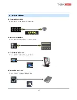
3. Installation

Example of Connection PTZ Camera No. 14 Pin Connector

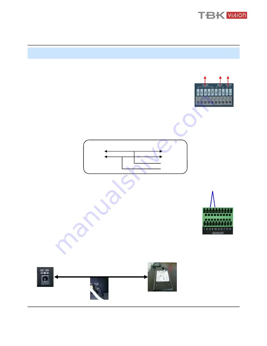
6. Alarm/Relay/PTZ Connection (4 channel model)

ALARM

Alarm Input -

IN1, IN2, IN3, IN4

: Connect Sensor Input by Channel

GND

: Connect to Ground

RELAY

Alarm Output – ‘NO, NC’ : Check Alarm Output Type (Normal Open or Normal Close)

and connect to ‘NO, NC’

‘COM’ : Connect remain Grounding Conductor

RS-485

Connect PTZ Camera – ‘D+, D-’ : Connect PTZ Camera Control Line (+ , – Terminal)

PTZ 14 Pin Cable

R+

R-

T+

T-

RS485

D+

D-

7. Power Connection (4 channel model)

Connect DC Power Input Terminal and Specific Adaptor

4 Channel Model

8 / 16 Channel Model

ALARM

1 2 3 4 G

Panic

PTZ

+ -

SENSOR

Sensor Input - Sensor Input 1-8, G for Ground

ALARM OUT

Alarm Output – Alarm Output 1-4, G for Ground

PTZ

Connect PTZ Camera : Connect PTZ Camera Control Line (+ , – Terminal)

PANIC

For Urgent Recording by preset panic setup 

Summary of Contents for 7000 SERIES

Page 1: ...ware Version Ex Factory Date 050905 060829 061001 061201 070212 Thank You Thank you for purchasing our Digital Video Recorder Before operating the system please read this User s Manual thoroughly and...

Page 2: ...TO REDUCE FIRE OR SHOCK HAZARD DO NOT EXPOSE THE UNIT TO RAIN OR MOISTURE This installation should be made by a qualified service person and should conform to all local codes WARNING...

Page 3: ...e 2 Do not dismantle or assemble the product It may cause malfunction or fire 3 Enquire from your vendor for repair It may cause electric shock or fire if the repair is not done properly 4 Do not touc...

Page 4: ...power cord or use extension cord It may generate heat or cause fire 3 Do not touch the power cord with wet hands It may cause electric shock 4 Keep power cord dry and protect from humidity It may gene...

Page 5: ...t o r C o n n e c t i o n 1 7 5 C o m p u t e r C o n n e c t i o n 1 7 6 N e t w o r k C o n n e c t i o n 1 7 7 A l a r m R e l a y P T Z C o n n e c t i o n 1 8 8 P o w e r C o n n e c t i o n 1 8...

Page 6: ...t e m 3 3 5 E v e n t S e n s o r 3 9 6 D i s k M a n a g e m e n t 4 2 G o t o R e c o r d M e n u 4 3 1 R e c o r d i n g O p e r a t i o n 4 3 2 C on ti n uo us M o ti on R ec o r d Sc h ed ul e 4...

Page 7: ...sitivity levels 10 Simplex Duplex operation Triplex Video inputs 4 8 16 x 1Vp p CVBS 75ohms BNC looping inputs Monitor outputs 1 x CVBS S VHS VGA option Spot output 1 x 1Vp p CVBS 75ohms BNC Audio inp...

Page 8: ...lish Spanish Chinese Russian Slovak Hungarian Turkish German French Ethernet interface 10 100 Base TX RJ 45 Remote Function Live View Live Recording Search Set up Back up PTZ Control RS 485 interface...

Page 9: ...nfirm the contents when open package Basic Contents Remote Controller User Manual Remote Software CD AAA Battery X 2 12V Adaptor TBK 7004SA LX only Power Cable Option Contents HDD CD RW USB MOMORY DVR...

Page 10: ...K Camera 1 4 Alarm Sensor 1 4 Relay Out VCR VGA Monitor AV Monitor Remote Client PC Image Printer DVR Video In Video Out TCP IP Alarm Input Out Remote Controller CD RW Backup AVI Backup WEB Client USB...

Page 11: ...d SCR MODE Select Screen Division Mode or Rotation Mode SEARCH Go to Search Mode for Searching Data MENU Go to System Menu PTZ FOCUS Go to Camera PTZ FOCUS Control Search Controller Searching Recorded...

Page 12: ...set panic setup Search Controller Searching Recorded Data or Control Menu PTZ FOCUS Return Cancel Setup or Return to Previous Mode Play Retrieve video audio recorded in the HDDs of DVR Stop Stop the p...

Page 13: ...rt SVHS Output Video to SVHS Audio Out Output Audio Audio In Audio Input Related with 1 4 Camera Ethernet TCP IP Port for LAN Internet for Remote Surveillance Alarm Relay RS 485 Connect Port for Senso...

Page 14: ...memory stick and USB HDD backup VGA OUT Output Video to Computer Monitor via VGA Port S VHS S video main monitor output Audio Out RCA Audio output Audio In 4 RCA audio inputs RS 232C Serial interface...

Page 15: ...IRIS Mode Unused button s description is omitted Every button is operated same as front panel button Remote Controller can operate when remote controller sensor input part reacted each other If there...

Page 16: ...is iInstalled Setup Pin as Master and connect Pin at the Left End of Jumper When Two HDD are installed or add new HDD set First One as Master and the Other as Slave Slave Setup has No Pin When More t...

Page 17: ...DD Connect IDE Cable to Hard Disk It can connect two IDE Hard Disk at one cable port For the purpose of prevent confusing two equipments named Master Slave Master is one hard disk or first hard disk a...

Page 18: ...l One CD RW HDD at One IDE Cable set CD RW as Slave Jumper Setup as Master or Slave 15 1 CD RW Hard Disk Installation When install exchange or remove CD RW please System Off Properly and Disconnect DV...

Page 19: ...e Power Cable at the CD RW HDDx1 and CD RW Tip When Install Master HDD please connect 1 at IDE1 Port by Master Cable It means Master Connector which 1 connected with IDE1 Cable must 1 connect with HDD...

Page 20: ...Port in Back Side Panel 3 Monitor Connection Connect Monitor Terminal or S VHS Terminal to Monitor 4 Computer Connection Connect VGA OUT Terminal to Computer Monitor 5 Network Connection Connect Ether...

Page 21: ...Connect remain Grounding Conductor RS 485 Connect PTZ Camera D D Connect PTZ Camera Control Line Terminal PTZ 14 Pin Cable R R T T RS485 D D 7 Power Connection 4 channel model Connect DC Power Input T...

Page 22: ...nu Search cannot work 1 Power On 2 New HDD Format Select By Play Backward Play button When it finds two new HDDs it asks to format each Then choose Yes to format all HDDs If you format the first HDD o...

Page 23: ...ding Mode Picture of Power On after Finishing Installation 4 Display Check System status LEDs Power Indicates System On Off Record Indicates Recording On Off Network Indicates Network LAN Client conne...

Page 24: ...The initial display mode is set to either 8ch or 16ch mode 4 Display 2 Screen View Selection Select One Channel using the channel selection buttons 1 16 Use the display button to change the multi cha...

Page 25: ...vices Press PTZ Button to switch into PTZ mode Status Bar is replaced by PTZ controls 5 System Power Off System Log On User Account Types are Administrator Manager User Administrator Access All Functi...

Page 26: ...Search Recorded Date Time Move Cursor to Selected Date in Calendar Recorded Date Time Indicated by Gray Color Press Enter to Open Selected Date Recorded Time Appear at Under Side Press Enter at Selec...

Page 27: ...ct Start Date Finish Date for Searching Event Alarm Searching Alarm Event during the Selected 1 Period Motion Searching Motion Detected Event during 1 the Selected period Timer Searching Schedule Chan...

Page 28: ...vent Contents Camera No Event Searching Method User can Search Event by using Direction key Search Event press Enter at Selected Event from Event Occurrence Time Control Video is the same way as Time...

Page 29: ...on 1 1 2 3 4 After input Password press Enter to display Menu Initial Administrator Manager User Password is 1234 Showing Password as Password can be changed in System setup System User management Onl...

Page 30: ...een Camera Title Show Hide camera name on off Event Icon Show Hide event icon on off Border Show Hide border Grid on off in multi channel mode Border Color Select color of border Grid White Blue Red Y...

Page 31: ...hannel will go full screen on activation Motion pop up dwell motion pop up time 1 60sec Display mode select display mode VGA AV 1 3 SEQUENCE Press Enter then red border line will disappear Setup mode...

Page 32: ...6 Menu 1 4 SPOT OUT 29 Select camera channel for spot out User can see the selected channel via AV monitor...

Page 33: ...rt On Display Video is Hidden in Watch mode but Recording is On Title Setup Camera Name by Virtual keyboard Control the Monitor Bright Contrast Color Tint Setup value from 0 100 Color Setup is done ch...

Page 34: ...Protocol Select protocol of PTZ Camera Press button and setup the detailed PTZ Baud Rate Setup PTZ Communication Speed 2400 4800 9600 19200 38400 BPS PTZ Supplied Protocol Samsung MRX 1000 Samsung SC...

Page 35: ...rection Key and Press Enter at Selected Region Choose the Partial Motion Region channel by channel Sensitivity 1 10 Select All Select Entire Region Deselect All Cancel Region Setup Cancel Cancel Chang...

Page 36: ...e 4 System Basic Environment Setup 4 1 date time User should set the proper Time zone for your geographic location before adjusting the other settings Date time Set the present date time Date Format S...

Page 37: ...Setup Time zone as your location 2 Setup the Network Time server and press the Sync button 3 If correct time is not set automatically setup the date time manually 4 If don t follow instruction as abo...

Page 38: ...DNS to On set the DDNS properties user name password and domain name and reboot the system 3 To access the DVR using the name server address the format for the address is http user name domain Example...

Page 39: ...hin the DVR Server Setup the outgoing Mail server address Input the server address using the Virtual Keyboard Port Mail server port number default is port 25 Security For a mail server the requires ou...

Page 40: ...of 3 User Groups as Administrator Manager User Total 7 users for 3 User Groups can be made Input User ID Password Choose the Group Input the E mail Address It can edit User ID information E mail noti...

Page 41: ...rade by TBK 7008 7016 only User can do F W update by USB or CD device TBK 7008 7016 only TBK 7004 shall be upgraded by network only Press Press Select F W from the list Press START Factory default Use...

Page 42: ...sor 5 1 HDD Event Drive HDD connected location Smart Alarm On Off Check interval HDD checking Time 4 6 Control device TBK 7008 7016 only System ID Select system ID 1 254 Protocol Select protocol Baud...

Page 43: ...ted Relay as Latched Transparent Mode Type Setup Relay Type N Open or N Close Duration Setup Reacted Relay Time 5sec 5min or Until key in Operation Setup Alarm Sensor Connection Status enable disable...

Page 44: ...nput Sound 5 5 E mail Notification E Mail Notification will send an e mail to a list of recipients based on alarm video loss motion or HDD events Check or uncheck each type of condition that you want...

Page 45: ...halted and the system buzzer will activate Format Click START to Format HDD All Recorded data will be deleted from the HDD NOTE Any newly installed HDDs will be detected during the Power On Self Test...

Page 46: ...to Record Menu 1 Recording Operations Schedule Mode Choose the DAILY or WEEKLY Pre Event Recording Time Setup Pre Event recording Time 1 1 5 sec Post Event Recording Time Setup Post Event recording Ti...

Page 47: ...S Quality and Audio on each channel Continuous recording Icon Motion recording Icon Select an area channel time of day on the schedule grid and press enter to adjust its properties Set area as Timer C...

Page 48: ...ocks Press ENTER again to set up the resolution FPS quality and audio on each channel Select an area channel time of day on the schedule Press enter to select or deselect alarm recording If WEEKLY rec...

Page 49: ...6 Menu 4 Panic Setup TBK 7008 7016 only To setup each channel press enter Setup each channel Size FPS Quality Audio By using panic button of front panel can record urgently as setup 46...

Page 50: ...e Change the Title of Backup by virtual keyboard Event Select Attach Event Text File in Backup Start Start Backup Tip Compatible CD Writer Models are LG GCE 8526B GCE 8527B SAMSUNG SW 252F TS H292A SH...

Reviews: