background image


                                                                                        BS Smart battery charger 


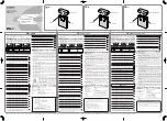
3.2    Optional remote control RBS installation 

R

BS can be installed by surface mounting or wall mounting.   

Please see following instructions:   


Surface Mounting Installation 


Wall Mounting Installation 

Summary of Contents for BS1225

Page 1: ......

Page 2: ...BS Smart battery charger...

Page 3: ...BS Smart battery charger WARNING HIGH VOLTAGE INSIDE CAUTION THE DC FUSE MUST HAVE BEENTURNED OFF BEFORE SERVICING MADE IN CHINA...

Page 4: ...of the use of such information TBB offers standard warranty with its products taking no responsibility for direct or indirect loss due to equipment failure About this Manual This manual describes our...

Page 5: ...e 5 2 3 1 BS1225 3 BS1240 3 BS2412 3 BS2420 3 5 2 3 2 BS1210 5 2 3 3 Optional remote control RBS 6 3 Installation 7 3 1 BS installation 7 3 2 Optional remote control RBS installation 9 4 Operation 10...

Page 6: ...ld water It is imperative to seek medical treatment from a doctor with injuries caused by acid DO NOT disassemble the charger by yourself which may result in a risk of electrical shock or fire Always...

Page 7: ...g slave charger for starter battery Sophisticated TBB premium II multiple stages charging algorithm for lead acid battery Suitable for lithium batteries Automatic temperature compensation charging Aut...

Page 8: ...nsating the voltage drop on the cable ensuring the correct charging current and voltage is delivered the battery Charging current adjustable Using the multifunctional smart button user can choose the...

Page 9: ...am 2 2 Naming Rules figure explanation Series name BS BS battery charger Rated DC voltage 12 12V 24 24V Rated DC current 10 10A 12 12A 20 20A 25 25A 40 40A Rated AC input N A 220 230V 110 110V Outputs...

Page 10: ...BS Smart battery charger 5 2 3 Product size 2 3 1 BS1225 3 BS1240 3 BS2412 3 BS2420 3 2 3 2 BS1210...

Page 11: ...BS Smart battery charger 6 2 3 3 Optional remote control RBS...

Page 12: ...art battery charger 7 3 Installation 3 1 BS installation BS can be installed on a horizontal surface or vertically on a wall Please see following instructions Hole size BS1225 3 BS1240 3 BS2412 3 BS24...

Page 13: ...rtical Installation Horizontal Installation ntal Installation Hole size 108 100 20mm M5 20mm M5 20mm M5 20mm Hole size BS1210 Ensure clearance on both sides of BS unit upon installation A recommended...

Page 14: ...attery charger 9 3 2 Optional remote control RBS installation RBS can be installed by surface mounting or wall mounting Please see following instructions Surface Mounting Installation Wall Mounting In...

Page 15: ...ng the BS charger is in the fault indicator When LED1 is ON they are the working status indicator No LED Color Status Description 1 LED 1 Green ON Charging status indication Slow flashing flash once e...

Page 16: ...arging ON ON Blue Battery type is GEL ON ON Red Charging current is 20A 12V40A Charging current is 15A 12V25A Charging current is 10A 24V20A Charging current is 6A 24V12A In addition to 12V10A model O...

Page 17: ...s 20A 24V20A Charging current is 12A 24V12A In addition to 12V10A model ON Quick flashing Red Battery not connected or reverse polarity alarm ON Slow flashing Green Set to power supply mode OFF Slow f...

Page 18: ...tery Starter battery connector 3 Output Service battery connector 4 Sensor Battery temperature and voltage sensor connector 5 Monitor Remote panel connector 6 Setting Select Setting button Figure 4 4...

Page 19: ...e Display mode or Charger Current Display mode 2 Then long press the main button for 3s you can enter into the setting mode 3 By pressing the button you can set the battery type or charger output curr...

Page 20: ...LED1 is green it is in the indication of charging status You can also set this battery charger into a power supply by pressing this button for 3secs entering into setting mode Status LED 1 LED2 LED3 L...

Page 21: ...g press the button for 3secs Battery type LED1 LED2 LED3 LED4 LED5 BLUE Green AGM GEL LFP WET If the LED1 is red it is in the indication of battery charger power You can also set the power after long...

Page 22: ...details If the user switch on the AC grid before the connection of battery there will be Battery not connected indication To exit this alarm short press the main button after well connecting the batte...

Page 23: ...ected to BS via a communication line In addition to 12V10A model and there are 3 LEDs and 2 buttons to check and set the status of BS synchronously NO Character Label Description 1 LED1 Power Mode 2 L...

Page 24: ...k flash three times every other two seconds Short circuit Quick flash four times every other two seconds Battery no connected or reverse polarity Quick flash five times every other two seconds Communi...

Page 25: ...ent A 25 25 40 40 Min battery voltage VDC 2V Efficiency 88 Input connector IEC socket Output connector M4 Screw 16mm Output 1 1 2 1 1 1 2 1 Ripple noise 200mVp p Regulation Accuracy 2 Cooling Fan cool...

Page 26: ...7 0V LFP 27 0V WET 27 4V Charging current A 12 12 20 20 Min battery voltage VDC 4V Efficiency 88 Input connector IEC socket Output connector M4 Screw 16mm Output 1 1 2 1 1 1 2 1 Ripple noise 200mVp p...

Page 27: ...T 13 7V Charging current A 10 Min battery voltage VDC 2 Efficiency 88 Input connector Cable of 1 5 meter with CEE 7 7 plug Output connector Fixed cable 2 5mm 1 meter Output 1 Ripple noise 200mVp p Reg...

Page 28: ...BS Smart battery charger 23...
Reviews: