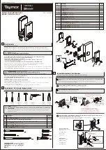


4
A. Attach the correct faceplate
Coloque la placa frontal correcta
B. Set the latch backset length
Ajuste de la longitud de la entrada del pestillo
C. Install the latch
Instale el pestillo
INSTALLING THE LATCH
INSTALACIÓN DEL PESTILLO
OR
O
OR
O
Installation
Instalación
CAUTION: Be sure the latch cam is upright before making any backset adjustment.
ADVERTENCIA: Asegúrese de que la leva del pestillo está en posición vertical antes de ajustar
la entrada.
OR
O
For 2-3/4" (70 mm)
backset.
Para entrada
de 2-3/4" (70 mm).
Wood block (not included)
Bloque de madera (no se incluye)
Drive-in latch
Pestillo rotativo
Tap latch flush
Coloque el pestillo
Edge of door
Borde de la puerta
Faceplate
Placa frontal
Edge of door
Borde de la puerta
Drive-in collar
Collarín rotativo
Flat head screwdriver
Destornillador de cabeza plana
Backset
Entrada
DD
2
8
3
2
8
3
2-3
/8”
(60
mm
)
180º
2 8
3
2 8
3
2 4
3
2
4
3
2-3
/4”
(70
mm
)
CAUTION /
ADVERTENCIA :
1.Please use four alkaline batteries for better performance.
2.Please set up the lock and perform bolt direction determination to complete the installation.
1.Use cuatro baterías alcalinas para obtener un mejor desempeño.
2.Configure la cerradura y determine la dirección del perno para completar la instalación.
A. Door bore options
Opciones de orificio de la puerta
B. Install the lock assemblies
Instale los ensambles de la cerradura
INSTALLING THE LOCK ASSEMBLIES
INSTALACIÓN DE LOS ENSAMBLES DE LA CERRADURA
Thread the cable through
the hole and under the latch.
Pase el cable a través del
orificio y por debajo
del pestillo.
Interior
Interior
Exterior
Exterior
The latch bolt MUST be in
retracted position.
El perno del pestillo debe
estar en posición retraída.
1
2
3
4
5
6
7
8
9
C
0
The bulged part of the mounting plate must face
towards the door.
La parte cóncava de la placa de montaje debe
estar hacia la puerta.
Slide the cable through the notch in
mounting plate.
Deslice el cable a través de la ranura
de la placa de montaje.
for Ø 2-1/8” (54 mm)
para Ø 2-1/8” (54 mm)
for Ø 1-1/2” (38 mm)
para Ø 1-1/2” (38 mm)
AA
BB
The correct hole sizes.
Ø 2-1/8” (54 mm)
Los tamaños correctos de los orificios.
Ø 2-1/8” (54 mm)
A
A
A
A
A
A
A
A
Download APP
on the App Store
and Google Play
Descarga la aplicación en
App Store y Google Play
Install batteries
Instalar Baterias
Install battery cover
Instalar la cubierta
de la batería
Set Admin Code by entering
4-8 digits PIN code and press
Establezca el código de
administrador introduciendo
el código PIN de 4-8 dígitos y presione
Repeat Admin Code and
press to complete setup.
The lock will automatically
set up bolt direction
after Admin Code is set.
Repita el código de
administrador y presione
para completar la configuración.
La cerradura configurará
automáticamente la dirección
del cerrojo después de configurar
el código de administración.
A
A
A
A
A
A
A
A
Scan QR code
Escanear código QR
A
A
A
A
A
A
A
A
Press [SET] button to
start Bluetooth enrollment
Presione el botón [SET] para iniciar
el registro de Bluetooth.
OR
O
A
A
A
A
A
A
A
A
A
A
A
A
A
A
A
A
Set Admin Code on APP
and press Complete
Establecer código de
administrador en la
aplicacióny presione
Completar
The lock will automatically
set up bolt direction
after Admin Code is set.
La cerradura configurará
automáticamente la
dirección del cerrojo
después de configurar el
código de administración.
1
2
3
4
5
6
7
8
9
C
0
TEMPLATE
PLANTILLA
NOTE: Double check your product for the correct hole sizes.
NOTA: Verifique nuevamente los tamaños correctos de los
orificios para su producto.
1-3/4”
(45 mm)
1-3/8”
(35 mm)
1-9/16”
(40 mm)
2”
(51 mm)
Ø 2-1/8” (54 mm)
2-3/4” (70 mm)
2-3/8” (60 mm)
Drill a 1” (25.4 mm) diameter
hole at the center of the door
edge.
Perfore un orificio de 1"
(25.4 mm) en el centro del
borde de la puerta.
Fold here.
Place on the door edge.
Doble aquí.
Coloque sobre el borde
de la puerta.
Backset
Entrada
Backset
Entrada
1-3/4”
(45 mm)
1-3/8”
(35 mm)
1-9/16”
(40 mm)
2”
(51 mm)
Ø 1-1/2” (38 mm)
2-3/4” (70 mm)
2-3/8” (60 mm)
Drill a 1” (25.4 mm) diameter
hole at the center of the door
edge.
Perfore un orificio de 1"
(25.4 mm) en el centro del
borde de la puerta.
Fold here.
Place on the door edge.
Doble aquí.
Coloque sobre el borde
de la puerta.
Backset
Entrada
Backset
Entrada
Insert screws (2) and tighten
Inserte los tornillos
(2) y apriete.
CC
The cable must be arranged as shown in the diagram.
El cable debe quedar como se muestra en el diagrama.
Note : The metal connector side should face outward.
Nota: El lateral del conector de metal debe quedar
hacia afuera.
Connect the cable firmly into connector port .
Conecte el cable al puerto conector firmemente.
Remove the Battery Cover
Retire la Tapa de la Batería
1
2
3
4
5
6
7
8
9
C
0


