V
-
21A
1
TAYLOR STUDWELDING
SYSTEMS LIMITED
OPERATING GUIDE
FOR
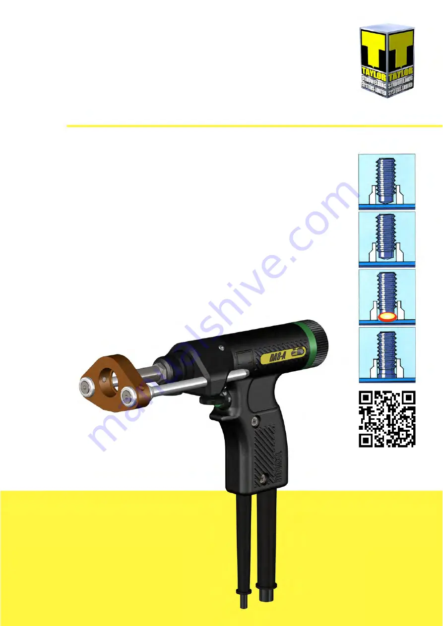
TYPE DA8
A
DRAWN ARC STUDWELDING PISTOLS
Page 1: ...V 21A 1 TAYLOR STUDWELDING SYSTEMS LIMITED OPERATING GUIDE FOR TYPE DA8 A DRAWN ARC STUDWELDING PISTOLS...
Page 2: ...5 INTRODUCTION TO STUDWELDING 6 MODEL VARIANTS 7 SET UP WELDING CHUCKS 8 SET UP WELDING STANDARD DA8 A 10 SET UP WELDING A1 A2 MODELS 12 SET UP WELDING A3 A4 MODELS 13 WELDING ALL MODELS 15 COMPONENT...
Page 3: ...dditional technical information please contact us directly details above or our local agent distributor details of agents etc can be obtained from us This guide contains important information which is...
Page 4: ...mselves and do not stand between the two earth return cables during welding 4 MAINTENANCE All cables must be inspected regularly to ensure that no danger exists from worn or damaged insulation or from...
Page 5: ...ble to stud weld without a ferrule This method is more commonly employed with welds having a duration of less than 100ms and this type of weld is referred to as short cycle stud welding Although no fe...
Page 6: ...own below DA8 A COMPLETE PISTOL PART NUMBER 99 101 063 DA8 A1 DA8 A2 99 101 064 99 101 065 Uses standard European Uses standard European Screw on chucks and Screw on chucks and long gas chucks long ga...
Page 7: ...pes may be found in the accessories section of this guide on pages 20 25 CD type chucks have an adjustable backstop which needs to be adjusted to suit whatever length of stud has been selected up to a...
Page 8: ...t Tighten the chuck into position using an appropriate wrench usually 14mm A F for Euro chucks see page 25 IMPORTANT Do not over tighten chucks This requires only hand tightening Over tightening may r...
Page 9: ...elding This must be done in three stages to ensure that the lift is set properly Stage one is to back the lift off so that the pistol can be properly positioned to set the lift To back the lift off tw...
Page 10: ...at the required lift is applied SET UP AND WELDING A1 A2 MODELS Having selected and where necessary prepared the chuck it can now be fitted to the pistol To begin remove the foot assembly by loosening...
Page 11: ...one in three stages to ensure that the lift is set properly Stage one is to back the lift off so that the pistol can be properly positioned to set the lift To back the lift off twist the rear end cap...
Page 12: ...aving selected and where necessary prepared the chuck it can now be fitted to the pistol Insert the chuck into the opening in the chuck nut and firmly push the chuck until it comes to rest at the bott...
Page 13: ...end cap adjuster has a click detent which allows the adjuster to stop every half turn This means that each half turn 0 5mm lift Therefore if 2mm of lift is required turn the rear end cap adjuster anti...
Page 14: ...iece Do not drape or wrap the pistol cables over or around yourself whilst operating the equipment Allow the cables to trail naturally to the floor Press the trigger Once welding has taken place Draw...
Page 15: ...LISTING ITEM QTY PART No DESCRIPTION 1 1 71 101 030 CONTROL PLUG 2 5 5 71 300 009 CONTROL CABLE per metre 3 1 81 101 051 WELD PLUG 4 5 71 300 002 WELD CABLE per metre 5 8 71 101 032 CABLE CLIP NOT SHO...
Page 16: ...04 BELLOWS RETAINING RING 4 1 71 101 233 BODY RING 5 1 71 101 203 REAR END CAP 6 4 Z120 04 020 SCREW 7 1 71 101 002 CHUCK NUT 3 2 1 6 5 4 SEE PAGE 20 25 FOR CHUCKS AND ACCESSORIES NOTE UNIQUE PARTS ON...
Page 17: ...No DESCRIPTION 1 1 71 101 200 PISTOL BODY MOULDING PAIR 2 1 71 101 223 DECAL STICKER 3 2 Z250 10 019 SCREW 1 2 3 PISTOL SCHEMATIC RED or BLUE 1 COIL BLUE or RED 2 4 PIN CONTROL YELLOW or GREEN 3 PLUG...
Page 18: ...Z700 05 022 TERMINAL 6 2 Z115 05 008 SCREW 7 1 71 101 201 TERMINAL PLATE 8 1 81 101 279 PUSHBUTTON SWITCH 9 2 Z225 08 914 SCREW 10 2 Z605 05 999 WASHER 11 1 71 101 214 CABLE CLIP 12 1 71 101 033 CABLE...
Page 19: ...3 042 COIL 7 1 71 101 210 COIL MOUNT 8 2 71 101 213 DETENT 9 1 71 101 211 COIL MOVER 10 1 71 101 011 CIRCLIP 11 2 Z800 04 026 PIN 12 1 71 101 219 INDICATOR LABEL 13 1 Z400 04 012 SCREW 14 1 71 101 209...
Page 20: ...IPTION 1 2 Z125 05 035 SCREW 2 2 81 101 003 FOOT WASHER FRONT 3 4 Z400 05 008 SET SCREW 4 1 81 101 336 FOOT ADAPTOR 5 2 81 101 001 FOOT WASHER REAR 6 2 72 103 092 LEG 110 LONG STANDARD WITH DA8 A or 2...
Page 21: ...Z400 05 008 SET SCREW 4 2 81 101 001 FOOT WASHER REAR 5 2 81 101 004 LEG 220 LONG STANDARD WITH DA8 A1 or 2 89 101 081 LEG 330 LONG OPTIONAL EXTRA 6 1 81 101 326 BELLOWS SUPPORT 7 1 89 101 244 BELLOWS...
Page 22: ...EXTRA 6 1 81 101 326 BELLOWS SUPPORT 7 1 89 101 244 BELLOWS 8 1 81 101 328 FRONT END CAP 9 2 Z400 05 004 SET SCREW 10 2 81 101 003 FOOT WASHER FRONT 11 1 81 101 325 FOOT ADAPTOR 12 1 PFE P06 M5M GAS...
Page 23: ...35 OPTIONAL GAS PARTS SPARES AS STANDARD THE A3 A4 MODEL VARIANTS ARE NOT FITTED FOR GAS BUT CAN BE RIGGED FOR GAS EASILY BY THE ADDITION OF THE OPTIONAL EXTRA PARTS BELOW 1 2 3 4 ITEM QTY PART No DES...
Page 24: ...UCKS FERRULE GRIPS USE STANDARD CHUCKS FERRULE GRIPS WITH THE STANDARD DA8 A PISTOL AND LONG GAS CHUCKS WITH THE DA8 A1 DA8 A2 MODEL VARIANTS Fig 1 Fig 2 Fig 3 OUR STOCK RANGE OF STANDARD EUROPEAN SCR...
Page 25: ...128 3 1 M8 NOZZLE 79 101 127 4 1 M6 NOZZLE 79 101 126 5 1 M5 NOZZLE 79 101 125 6 1 M4 NOZZLE 79 101 124 7 1 M3 NOZZLE 79 101 123 ACCESSORIES CD TYPE CHUCKS USE WITH DA8 A3 DA8 A4 PISTOL MODEL VARIANTS...
Page 26: ...ective The above mentioned products conform to the following European standards EN 60974 1 2012 ARC WELDING EQUIPMENT PART 1 WELDING POWER SOURCES EN 60974 10 2014 ARC WELDING EQUIPMENT PART 10 ELECTR...