USER INTERFACE
5-3
Models C709 & C717
User Interface
5
Important!
Make sure the level of mix in the hopper is
below the mix delivery hole in the feed tube. Failure to
follow this instruction may result in lower product quality
when normal operation is resumed.
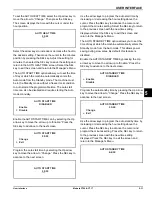
To resume normal operation, press the Auto key
.
When the machine cycles off, the product in the freezing
cylinder will be at serving viscosity. At this time, turn the
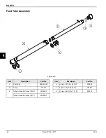
inner feed tube so the pin fits into the groove of the outer
feed tube. Install the air orifice.
Wash Key
The Wash key
(Model C709 or
Model C717)
illuminates when pressed. This indicates beater motor
operation. Standby or Auto modes must be canceled first
to activate the Wash mode.
Auto Key
The Auto key
illuminates when pressed. This
indicates that the refrigeration system has been
activated. In the Auto mode, Wash or Standby functions
are automatically canceled.
Note:
An indicating light will illuminate and an audible
tone will sound when a mode of operation has been
selected. To cancel any function, press the key again.
The light and the mode of operation will shut off.
Reset Mechanism
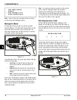
The C709 reset button is in the service panel on the left
side of the machine. The C717 reset buttons are in the
rear panel of the machine. Reset button(s) protect the
beater motor(s) from overloading. Should an overload
occur, the reset mechanism will trip. To properly reset the
freezer, place the power switch in the OFF position.
Press the RESET button firmly. Turn the power switch to
the ON position. Press the Wash key
/ and observe
the freezer's performance.
Note:
To clear the fault, see page 5-8.
If the beater motor is turning properly, press the Wash
key
/ to cancel the cycle. Press the Auto key
to
resume normal operation. If the freezer shuts down
again, contact your Taylor service technician.
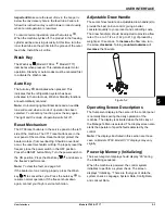
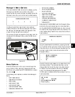
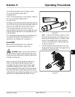
Adjustable Draw Handle
These machines feature an adjustable draw handle(s) to
provide the best portion control, giving a better,
consistent quality to your product and controlling costs.
The draw handle(s) should be adjusted to provide a flow
rate of 5 oz. to 7-1/2 oz. (142 g to 213 g) of product by
weight per 10 seconds. To
increase
the flow rate, turn
the screw
clockwise
. Turning
counterclockwise
will
decrease
the flow rate.
Figure 5-2
Operating Screen Descriptions
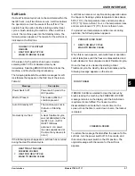
The fluorescent display in the center of the control panel
is normally blank during the daily operation of the
machine. The display is activated when the SEL key or
the Manager's Menu is selected. The display screen also
alerts the operator of specific faults detected by the
control.
Note:
The displays illustrated in this section are those
seen on Models C709. Model C717 displays may vary
slightly.
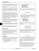
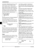
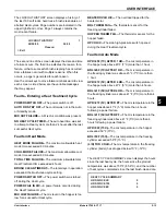
Power Up Memory (Initializing)
The seven-segment display should display “00” during
the initializing sequence.
When the machine is powered, the control system
initializes to perform a system check. The screen
displays “Initializing.” There are four types of data the
system checks: Language, System Data, Config Data,
and Lockout Data.
10354
Summary of Contents for C709
Page 8: ...1 4 TO THE INSTALLER Models C709 C717 To the Installer 1 Notes...
Page 36: ...5 16 USER INTERFACE Models C709 C717 User Interface 5 Notes...
Page 50: ...6 14 OPERATING PROCEDURES Models C709 C717 Operating Procedures 6 Notes...
Page 56: ...8 4 TROUBLESHOOTING GUIDE Models C709 C717 Troubleshooting Guide 8 Notes...
Page 58: ...9 2 PARTS REPLACEMENT SCHEDULE Models C709 C717 Parts Replacement Schedule 9 Notes...
Page 62: ...10 4 LIMITED WARRANTY ON EQUIPMENT Models C709 C717 Limited Warranty on Equipment 10 Notes...
Page 66: ...11 4 LIMITED WARRANTY ON PARTS Models C709 C717 Limited Warranty on Parts 11 Notes...


