OPERATING PROCEDURES
6-5
Model 736
Operating Procedures
6
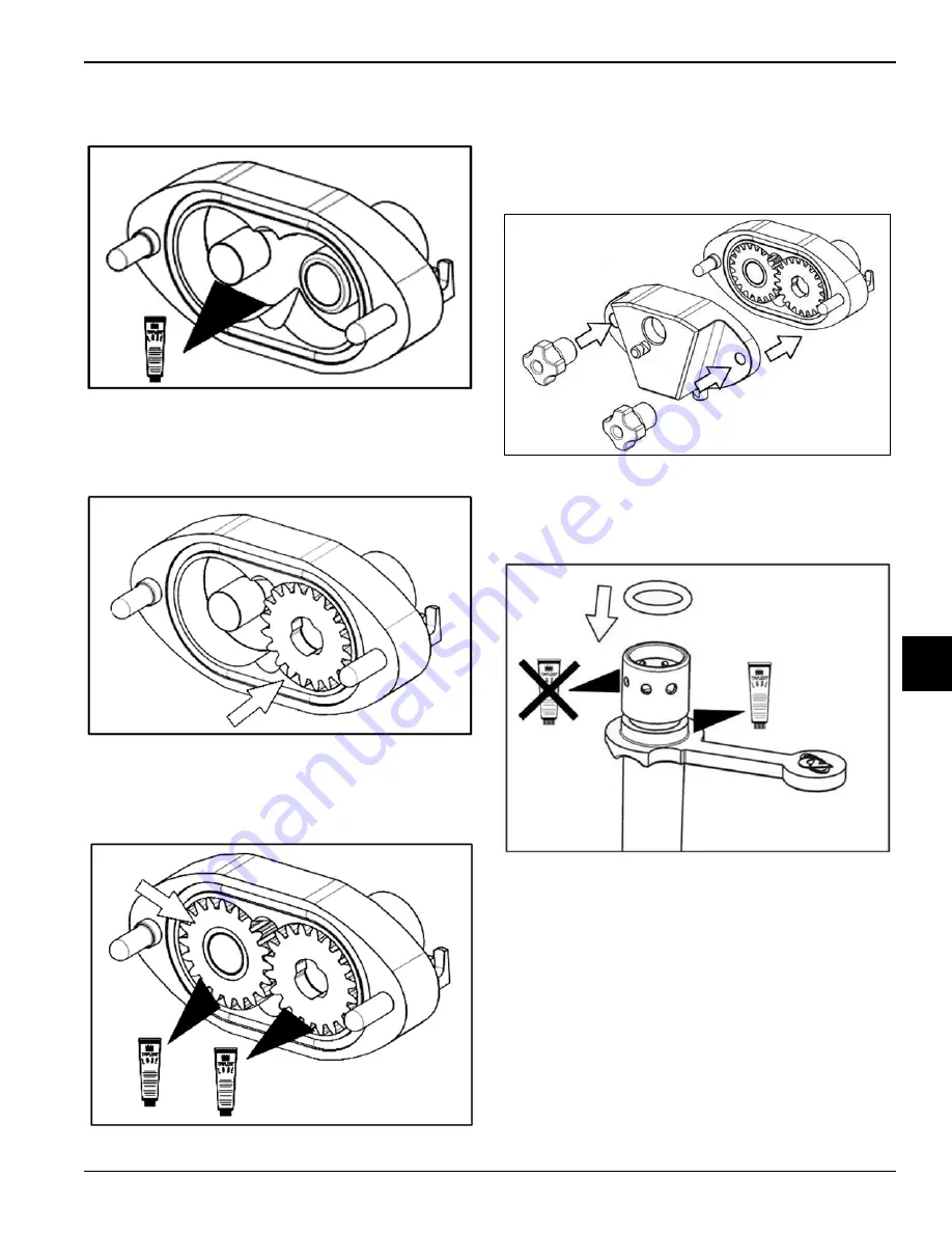
4. Lubricate the interior surfaces of the pump body
(the rear wall, pin, and bushing).
Figure 6-19
5. Insert the drive gear on the bushing; check that the
upper face of the gear is flush with the rim of the
pump body.
Figure 6-20
6. Insert the driven gear on the pin; check that the upper
face of the gear is flush with the rim of the pump
body. Lightly lubricate the flat faces of both gears.
Figure 6-21
7. Install the pump cover on the pump body studs.
Note:
The pump cover holes have different
diameters to prevent incorrect assembly.
Install the handscrews and tighten them equally to
make sure the pump is closed.
Figure 6-22
Note: Do not
lubricate the graduated holes.
8. Slide the regulator O-ring into the groove on the
liquid regulator and lubricate.
Figure 6-23
9. Insert the regulator spring into the liquid regulator
seat. Insert the pump valve into the spring so the
larger part is out of the spring.
Summary of Contents for 0736
Page 34: ...5 10 USER INTERFACE Model 0736 User Interface 5 Notes...
Page 54: ...8 4 TROUBLESHOOTING GUIDE Model 0736 Troubleshooting Guide 8 Notes...
Page 56: ...9 2 PARTS REPLACEMENT SCHEDULE Model 0736 Parts Replacement Schedule 9 Notes...
Page 60: ...10 4 LIMITED WARRANTY ON MACHINES Model 0736 Limited Warranty on Machines 10 Notes...
Page 64: ...11 4 LIMITED WARRANTY ON PARTS Model 0736 Limited Warranty on Parts 11 Notes...


