background image

Maintenance, Service, and Repair


Tires and Wheels 
Page 2

TIRE INFLATION

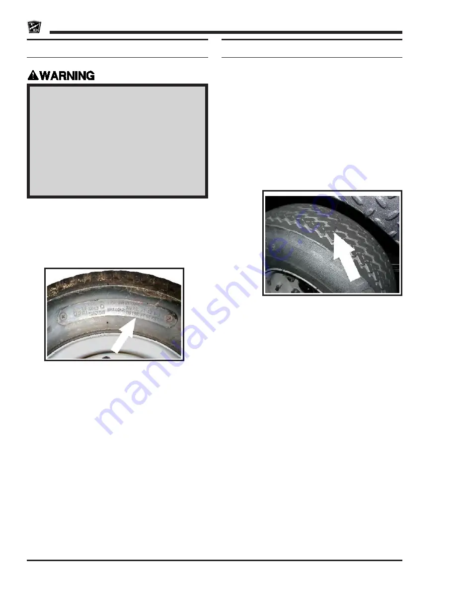
There are many tire options available with varying 
tire pressures. Refer to the side wall of your tire for 
information regarding the tire pressure for your tires.

The illustration to the right is an example of the side wall 
information on a tire.

Tire pressures must be checked when the tire is cold.

1. Make sure the key-switch is in the “OFF” 

position, then remove the key.

2. Place the forward-reverse switch in the 

center “OFF” position.

3. Set the park brake. 
4. Place blocks under the front wheels to 

prevent vehicle movement.

5. Disconnect the main positive and 

negative cables at the batteries.

TIRE INSPECTION

6.  Check the tire pressure. Refer to 

Tire Inflation


section for information on checking the tire 
pressure.

7.  Inspect the tire tread depth. Minimum recommended 

tread depth is 1/16-inch. There are a series of tread 
depth wear indicators around the circumference of 
the tire. They will appear as 1/2-inch bands across 
the tread as the tire approaches its wear limit (see 
illustration below). Replace the tire if any tread 
depth indicator can be seen or any part of the tread 
depth is 1/16-inch or less. Refer to 

Replace the 

Tire

 section for information regarding replacing 

the tire.

8.  Inspect for uneven tire wear on the front tires. 

Uneven tire wear could be a result of an improperly 

inflated tire or a misaligned or damaged front end.

Note:  Refer to 

Tire Inflation

 section or Steering 

Component Service section for information 

on  proper  tire  inflation  or  front  end  wheel 

alignment.

9.  Inspect the inner and outer side walls for cracks. 

If any cracks are seen, then the tire should be 
replaced. Refer to 

Replace the Tire

 section for 

information regarding replacing the tire.

10. Inspect the valve stem for cracks. If any cracks are 

seen, then the valve stem should be replaced. It is 
also recommended that the valve stem be replaced 
whenever the tire is replaced.

Note:  Refer to Replace the Tire section for 

information regarding replacing the valve 
stem.

11. Inspect the tread and side walls for debris in the 

rubber that could lead to a puncture. If any debris is 
found it should be removed and the tire inspected 
for a leak.

Summary of Contents for SC 0-90

Page 1: ...AINTENANCE This manual contains important information regarding the safe operation and maintenance of this vehicle Serial number Starting 171712 Ending 191319 Models Inlcuded SC 090 24 SC 0 90 24 volt...

Page 2: ......

Page 3: ...parts or service should be obtained through your local dealer A dealer locator can be found on the Taylor Dunn website at www taylor dunn com If you do not have access to the internet you can call th...

Page 4: ...n invaluable asset and it is an asset we cherish and protect Our guiding principle is to provide application specific solutions which are reliable efficient and economical Our domestic and internation...

Page 5: ...ble of Contents Introduction About this manual 2 Who Should Read This Manual 2 Responsibilities 2 How To Use This Manual 3 Conventions 3 How to Identify Your Vehicle 4 Taking Delivery of Your Vehicle...

Page 6: ...pplicable models and serial numbers on the front cover Please be aware of all cautions warnings instructions and notes contained in this manual RESPONSIBILITIES Of the Owner The owner of this or any T...

Page 7: ...entions Symbols and or words that are used to define warnings cautions instructions or notes found throughout this manual Refer to the examples below Note Alerts the reader to additional information a...

Page 8: ...Industrial Trucks and with all applicable portions of the American National Standard for Personnel and Burden Carriers ANSI B56 8 This vehicle is not designed to be driven on public roads or highways...

Page 9: ...Dunn vehicle is a factory authorized service technician Repairs made by unauthorized personnel may result in damage to the vehicles systems which could lead to an unsafe condition resulting in severe...

Page 10: ...Page 6 Notes...

Page 11: ...ry Motor Control Chargers Wire diagrams Replacement Parts Appendix Model SC 090 24 SC 0 90 24 Volt System Service and Repair Manual Section Index This quick reference section index guide will assist y...

Page 12: ...Notes...

Page 13: ...e Pedal 6 Park Brake 6 Charger Interlock 6 Foot Interlock Switch 6 Reverse or Motion Alarm Optional 6 Vehicle Operation Guidelines 7 Safety Guidelines 7 Starting 7 While driving 7 Loading and Unloadin...

Page 14: ...ical Gear Oil Bath Direct Gear Drive Motor DC 3 35 kW 935 rpm 4 5 hp Series Wound Maximum 16 kph 10 mph Recommended Speed Brakes Rear Wheel Mechanical Drum Hand Operated Park Brake Steering Clover Lea...

Page 15: ...h in the center OFF position 3 Set the park brake 4 Place blocks under the front wheels to prevent vehicle movement 5 Disconnect the main positive and negative cables at the batteries DRIVER TRAINING...

Page 16: ...ion Push the bottom of the switch to engage the reverse direction DO NOT SWITCH from forward to reverse or vice versa while the vehicle is in motion Make sure the vehicle is completely stopped before...

Page 17: ...ding The vehicle needs charging if it is in the yellow zone During and immediately following charging the needle will be in the red zone to the right The needle will move through the green zone toward...

Page 18: ...terlock is designed to disable the vehicle from being driven while the AC charger cord is plugged into a functioning power source Illustration is not available Reverse or Motion Alarm Optional The rev...

Page 19: ...es Only qualified and trained operators may drive this vehicle Drive only on level surfaces or on surfaces having an incline of no more than 10 5 6 degrees Drive slowly when making a turn especially i...

Page 20: ...vehicle while it is being towed Be sure the driver uses the brakes when the towing vehicle slows or stops Do not tow the vehicle faster than 5 m p h or its maximum designed speed whichever is lower I...

Page 21: ...n indication of a charging problem charger will also be beeping Refer to the Charger Troubleshooting section for information on error codes Charging State LED1 LED2 LED3 0 to 50 Blinking OFF OFF 50 to...

Page 22: ...le Controls in this section for information on how to read the BSI Do not discharge the batteries beyond a normal discharge as indicated on the BSI Refer to Vehicle Controls in this section for inform...

Page 23: ...le battery hydraulic system 500 Adjust service and park brake systems Inspect all steering linkages and hardware Tighten steering shaft to steering gear coupler if equipped Lubricate the vehicle Wash...

Page 24: ...n Extreme temperature Bumpy dusty or ill maintained roads Excessively wet areas Corrosive or contaminated areas Frequent loading of vehicle at near capacity Use on multiple shifts 2 Any deficiencies f...

Page 25: ...TABLE OF CONTENTS Maintenance Guidelines 2 Troubleshooting Guide 3 Lubrication Chart 4 General Maintenance...

Page 26: ...s Do not use an open flame to check level or leakage of battery electrolyte Do not use open pans of fuel or flammable fluids for cleaning parts Only properly trained and authorized technicians should...

Page 27: ...ering Shaft Loose Steering Linkage Lack of Power or Slow Operation Brakes or Parking Brakes Dragging Worn Drive Gears Defective Speed Control Abnormal Noise Worn Drive Gears or Bearings Worn Front Rea...

Page 28: ...Purpose Grease 2 Front Fork Spindle Bearings 1 General Purpose Grease 3 Steering Shaft Gears 1 General Purpose Grease 4 5 Front Wheel Bearings 1 or 2 High Temperature Wheel Bearing Grease 6 Steering C...

Page 29: ...TABLE OF CONTENTS Inspect the Front Wheel Bearings 2 Adjust Front Wheel Bearings 3 Front Axle Removal and Installation 4 Removal 4 Replace Front Wheel Bearings 5 Front Axle...

Page 30: ...r any grinding noise Any noise may be an indication of worn or damaged wheel bearings Note Refer to the Replace Front Wheel Bearings section for information regarding the replacement of the wheel bear...

Page 31: ...ngs section for information regarding the replacement of the wheel bearings 9 Lower the vehicle 10 Reconnect the main positive and negative cables at the batteries 11 Remove the blocks from behind the...

Page 32: ...information regarding tightening the front axle Note If your vehicle is equipped with two axle nuts the nuts should be tightened equally so that the same number of axle threads are visible on both end...

Page 33: ...injury REPLACE FRONT WHEEL BEARINGS 6 Remove the front axle and wheel s Refer to Front Axle Removal and Installation section for information regarding removing the axle 7 Remove the spacers seals and...

Page 34: ...Front Axle Page 6 Notes...

Page 35: ...enter the Steering Wheel 3 Inspect the Steering Components 5 Steering Wheel and Bushings 5 Steering Chain 5 Pillow Blocks 6 Fork Bearings 7 Adjust the Steering Shaft 8 Replace the Steering Wheel 9 Rep...

Page 36: ...ering shaft should be level If it is not level then perform the following A Raise the front wheel approximately 1 inch off of the ground B Remove the fork spindle bearing cap C Loosen the fork nut unt...

Page 37: ...heels tied in position may cause loss of control of the vehicle resulting in severe bodily injury and or property damage 6 Position the front fork in the straight ahead position and tie it off so that...

Page 38: ...all play from the steering chain 14 Install new safety wire and tie off as shown in the illustration 15 Untie the front fork 16 Reconnect the main positive and negative cables at the batteries 17 Rem...

Page 39: ...slot corners should be 90 degrees with a small radius If the corners are excessively rounded or the sides are tapered then the steering wheel should be replaced Steering shaft and sprocket Steering Ch...

Page 40: ...s to prevent vehicle movement 5 Disconnect the main positive and negative cables at the batteries Pillow Blocks Note The two pillow blocks will wear at the same rate If one is worn out then both block...

Page 41: ...Failure to use lifting and support devices of rated load capacity may result in severe bodily injury FORK BEARINGS 6 Raise the front of the vehicle and support with jack stands 7 Inspect for lateral p...

Page 42: ...rew 9 Rotate the steering wheel from left to right Any roughness is an indication of being too tight Repeat the procedure and hold less tension on the gears while setting the collar 10 Reconnect the m...

Page 43: ...d off of the steering wheel sprocket 9 Remove the steering wheel 10 Install the steering wheel in reverse order Note Lightly lubricate the steering wheel shaft 11 Align the steering Refer to section F...

Page 44: ...ng the front axle If the fork was replaced with a new fork the front end should be realigned Refer to section Front End Alignment for information regarding aligning the front end 10 Lower the wheels t...

Page 45: ...hanism Operation 3 Inspecting the Auto Adjust Brake Mechanism 3 Brake Shoes 4 Brake Drum 4 Inspect the Parking brake 5 Wheel Park Brake 5 Adjust the Service Brakes 6 Adjust the Brake Linkage 6 Adjust...

Page 46: ...rrently supply asbestos fiber brake pads shoes with any vehicle However there is the possibility that the original brake pads shoes were replaced with aftermarket pads shoes containing asbestos Since...

Page 47: ...ight brake Do not adjust the brake by means of the brake cables as this will cause misoperation of the brakes If you hear a single clunking noise while braking it may be due to misadjustment of the br...

Page 48: ...ote If this is a riveted lining then the measurement must be to the top of the rivets It is recommended to replace the left and right side brake shoes as a set Brake Drum Do not use a brake drum that...

Page 49: ...causing severe bodily injury and or property damage 1 Make sure the key switch is in the OFF position then remove the key 2 Place the forward reverse switch in the center OFF position 3 Set the park...

Page 50: ...and support the vehicle Failure to use lifting and support devices of rated load capacity may result in severe bodily injury 1 Place the forward reverse switch in the center OFF position 2 Place bloc...

Page 51: ...justment handle 6 Release the park brake 7 Rotate the knob on the end of the park brake handle to adjust the brake Clockwise to tighten Counter clockwise to loosen 7 Set the park brake 8 Reconnect the...

Page 52: ...d or severe bodily injury 6 Raise the rear of the vehicle and support with jack stands 7 Using the appropriate procedure remove the brake drum 8 Release the park brake 9 Remove the tension springs 10...

Page 53: ...S Inspecting the Motor Brushes 2 Motors with internal cooling fans 2 Motor Removal and Installation 2 Motor Inspection 2 Replacing Brushes Armature Bearing 4 Repairing the Commutator 5 Service Limits...

Page 54: ...forward reverse switch in the center OFF position 3 Set the park brake 4 Place blocks under the front wheels to prevent vehicle movement 5 Disconnect the main positive and negative cables at the batte...

Page 55: ...or information regarding machining the commutator 7 Visually inspect the armature windings for burnt insulation Burnt insulation is a direct result of motor overheating and could lead to a shorted arm...

Page 56: ...bearing in the rear housing 6 While supporting the inner race of the bearing press the armature into the bearing 7 Push the motor brushes into the brush holder until the brush spring snaps into place...

Page 57: ...the commutator segments 6 Measure the commutator undercut depth in 5 places around the commutator If any one of the measurements is less than the minimum undercut depth specified in Service Limits the...

Page 58: ...y test of each winding is all that is required to determine if the motor is at fault Motor Specification Number Undercut Depth Commutator Di ameter min Brush Length min Resistance Ohms 75 F mm inches...

Page 59: ...TABLE OF CONTENTS Transmission Check Oil Level 2 Change Oil 2 Motor 3 Removal 3 Installation 3 Rear Axle 3 Differential Case 4 Disassemble 4 Assemble 6...

Page 60: ...nd the wheels 12 Test drive the vehicle Level Plug viewed from in front of the right rear wheel Fill Level Plug in transmission cover CHECK OIL LEVEL Park the vehicle on a level surface 6 Place a drai...

Page 61: ...he end of the transmission input shaft Grease applied to these areas may result in premature failure of the armature bearing REAR AXLE Note The tire wheel assembly must be removed for these procedures...

Page 62: ...sembly Refer to Rear Axle section for information on removing the axles 4 Suspend the differential case over a drain pan that can hold a minimum of 2 quarts of oil 5 Remove the differential case cover...

Page 63: ...shaft through the bearing just enough to allow clearance for an ID bearing puller Do not attempt to drive the shaft out of the opposite end of the transmission 13 Remove the intermediate bearing with...

Page 64: ...ring is loose then it must be replaced Note All internal components should fit easily together Do not hit any shaft or component with a hard metal hammer or punch Note Pre lube all bearings seals and...

Page 65: ...new bore plugs Note Drive the bore plugs until they are firmly seated against the snap rings 10 Install the final drive gear onto the differential housing Torque the nuts to 35 45 ft lbs 11 Install t...

Page 66: ...Transmission Page 8 Notes...

Page 67: ...TABLE OF CONTENTS Tire Inflation 2 Tire Inspection 2 Replace the Front Tire Wheel 3 Replace the Rear Tire Wheel 3 Replace the Tire pneumatic 3 Repair the Tire pneumatic 4 Tires and Wheels...

Page 68: ...ad as the tire approaches its wear limit see illustration below Replace the tire if any tread depth indicator can be seen or any part of the tread depth is 1 16 inch or less Refer to Replace the Tire...

Page 69: ...To replace the tire the tire wheel assembly must be removed from the vehicle Refer to Replace the Tire Wheel section for information on removing the tire wheel assembly Tire replacement should only be...

Page 70: ...wheel coming off of the vehicle causing severe bodily injury and or property damage REPAIR THE TIRE PNEUMATIC Note To properly repair a puncture the tire must be removed from the wheel Refer to Replac...

Page 71: ...BLE OF CONTENTS Battery Service Cleaning 2 Testing 3 Charging 4 Watering 5 Replacing 6 volt batteries only 6 Moist Charge Batteries 7 Storage and Returning to Service 8 Storage 8 Returning to Service...

Page 72: ...may result in severe bodily injury and or property damage Battery electrolyte will stain and corrode most surfaces Immediately and thoroughly clean any surface outside of the battery that the battery...

Page 73: ...the battery A conductive object that comes in contact with the battery terminals will initiate a short circuit of the battery This could cause the battery to explode resulting in severe bodily injury...

Page 74: ...specific gravity of each cell in the battery pack If after charging none of the cells exceed a hydrometer reading of 1250 then there may be a fault in the charging system If the charging system check...

Page 75: ...n contact with the battery terminals will initiate a short circuit of the battery This could cause the battery to explode resulting in severe bodily injury and or property damage Battery electrolyte i...

Page 76: ...be replaced 9 Remove all battery jumpers from both posts of the battery or batteries being replaced Note It is recommended to replace the battery jumpers when replacing the batteries 10 Remove the bat...

Page 77: ...that is formulated to be used in wet lead acid batteries and is available at most automotive parts distributors that carry batteries When torquing battery hardware use a backup wrench on the battery...

Page 78: ...l source It cannot be disconnected or neutralized Do not drop any tool or conductive object onto the battery A conductive object that comes in contact with the battery terminals will initiate a short...

Page 79: ...tion for information regarding checking the electrolyte level 8 Test the batteries Refer to Testing section for information on testing the batteries 9 The batteries are now ready to be put back into s...

Page 80: ...Batteries Page 10 Notes...

Page 81: ...Table of Contents Motor Controller Motor Controller Remove Install 2 Inspect 2 Troubleshooting 2 Repair Adjustments 3 Adjustments 3 Hardware Torque 4...

Page 82: ...que per specification listed in the table at the end of this section 4 If equipped with the 7 pin in line connector install silicon dielectric grease 94 422 10 5 3 ounce tube into the harness plug bef...

Page 83: ...reversing direction 3 Current Limit Maximum current not available on all controls These adjustments are accessed by removing the button head screws in the housing The control may need to be removed fr...

Page 84: ...Controller Page 4 HARDWARE TORQUE If hardware is not listed here refer to standard torque values in the appendix Description Inch Pounds Newton Meters Terminal hardware 72 8 13 Adjustment plugs 8 0 90...

Page 85: ...TABLE OF CONTENTS Remove Install 2 Troubleshooting 2 Charger...

Page 86: ...rranty and may result in incorrect operation of the charger or premature failure TROUBLESHOOTING Troubleshooting control system is not included in this manual All electrical troubleshooting informatio...

Page 87: ...refer repair to a qualified licensed electrician Depending on the charging system two different color codes are used for the AC power source United States Standard 120 Volt White Neutral Black Hot Gre...

Page 88: ...Wire Diagrams Page 2 Notes...

Page 89: ...s optional 10 Instrument Panel dash 11 Knee Pad and Floor Mats optional 12 Ladders and Strobe Light optional 14 Lift Out Battery Box optional 15 Miscellaneous Electrical 16 Motor 18 Signet Charger 20...

Page 90: ...Illustrated Parts Parts Page 2 Axle Front and Fork...

Page 91: ...No Part No Description Qty 1 88 229 81 3 4NC Lock nut 1 or 2 2 88 228 61 3 4 SAE Flat washer 1 or 2 3 15 010 20 Axle single wheel 1 4 16 010 00 Spacer 2 or 4 5 15 011 00 Axle dual wheel 0 or 1 6 14 03...

Page 92: ...10 97 Lock nut 23 41 344 98 Brake assembly 24 41 344 99 Brake assembly 25 41 126 99 Axle shaft Right 26 41 126 98 Axle shaft Left 27 88 527 11 Cotter pin 28 45 303 20 Seal 29 45 303 10 Seal 30 80 480...

Page 93: ...arger 77 047 00 244AH T 145 77 047 50 250AH TD 250 77 047 80 244AH T 145 Moist charge dry 77 048 00 250AH J 250 77 048 80 250AH J 250 Moist charge dry 77 051 00 160AH Gell Note requires special charge...

Page 94: ...Illustrated Parts Parts Page 6 Brake Linkage...

Page 95: ...ad 1 6 80 410 20 Bushing assembly 2 7 88 109 81 3 8NC Lock Hex nut 4 88 100 09 3 8NC x 3 4 Hex bolt 4 8 88 527 11 Cotter pin 6 9 00 150 61 Treadle weldment 1 10 96 763 00 Clevis 1 11 88 099 80 5 16NF...

Page 96: ...94 313 00 Battery Warning 1 2 94 319 00 Battery Disconnect 1 3 94 382 00 Treadle operation 1 4 94 301 43 Arms and hand inside 1 5 94 313 20 Safety warning 1 6 94 384 01 Not a motor vehicle 1 7 94 384...

Page 97: ...per chain cover 1 2 90 501 00 Deck standard 1 3 79 511 00 Charger cord holder 1 79 575 30 AC cord 8 foot 1 79 530 00 Strain releif for AC cord 1 4 03 150 43 Lower chain cover 1 5 03 150 28 Treadle pla...

Page 98: ...1 2NC Hax nut 4 88 148 62 1 2 Split lock washer 4 Head and Tail Lights optional Illustration not available HEAD and TAIL LIGHTS Item No Part No Description Qty 72 005 00 Head light 1 or 2 72 072 00 Re...

Page 99: ...1 71 120 90 Replacemet key for 1 key 2399 1 71 121 20 Key switch keyed unalike 0 or 1 2 71 039 11 Accesory switch SPST 0 or 1 3 71 039 11 Accesory switch SPST 0 or 1 4 74 009 10 Battery Status Indicat...

Page 100: ...Illustrated Parts Parts Page 12 Knee Pad and Floor Mats optional...

Page 101: ...me of printing Parts Page 13 KNEE PAD and FLOOR MATS Optional Item No Part No Description Qty 1 01 103 20 Floor mats 1 2 01 159 10 Knee pad 1 3 88 837 11 14 x 1 Phillips head screw 2 Not shown 94 440...

Page 102: ...lit lock washer 8 88 089 80 5 16NC Hex nut 8 LIGHT STROBE Item No Part No Description Qty 1 88 029 80 8 32 Hex nut 3 2 88 028 62 8 Split lock washer 3 3 88 025 06 8 32 x 1 2 Truss head machine screw 3...

Page 103: ...available at time of printing Parts Page 15 Lift Out Battery Box optional LIFT OUT BATTERY BOX Item No Part No Description Qty 75 077 10 Harness to battery 2 75 077 14 Harness to vehicle 1 77 983 00 L...

Page 104: ...Illustrated Parts Parts Page 16 Miscellaneous Electrical Miscellaneous Wire Harness Clamps 2 3 17 16 15 18 1 2 Motion Alarms 20 19 Battery Status Meters Hour Meters 5...

Page 105: ...96 631 10 shown Clamp Rubber Lined 1 0 ID 96 631 15 not shown Clamp Rubber Lined 1 1 2 ID 17 96 624 00 Clamp 1 4 Jiffy Clip 96 625 00 not shown Clamp 5 16 Jiffy Clip 18 96 626 00 Clamp 7 8 Jiffy Clip...

Page 106: ...Illustrated Parts Parts Page 18 Motor...

Page 107: ...0 421 10 70 412 30 70 412 20 70 170 00 70 109 00 70 417 00 80 212 00 70 421 00 88 067 17 88 067 22 203 21 4001 or XP1820A 70 072 41 85 403 00 70 173 00 70 170 10 1 XP 1786 or DD3 4004 70 052 40 70 412...

Page 108: ...ide the charger Note The charger AC cord is an intergral part of the charger When replacing the charger do not cut and splice the AC cord Cutting the AC cord will void the charger warranty Note The Si...

Page 109: ...ee note 79 309 42 48 volt charger assembly see note Model HBS for GEL Batteries PART DESCRIPTION 79 303 42 36 volt Charger assembly see note 79 309 43 48 volt charger assembly see note Model HB for Fl...

Page 110: ...Illustrated Parts Parts Page 22 Speed Control Panel...

Page 111: ...0 Circuit Breaker 135 amp 1 9 73 004 20 Horn 12 V 1 10 88 089 80 Nut 5 16 NC 4 11 88 088 62 Lock Washer 5 16 4 12 88 088 11 Bolt 5 16 NC x 1 Hex Hd 4 13 61 838 41 Bus Bar 5 8 x 1 1 2 Hole Centers 2 14...

Page 112: ...Illustrated Parts Parts Page 24 Steering Linkage...

Page 113: ...1 8 96 900 00 Turn buckle 2 9 88 080 16 5 16NC x 2 Hex bolt 4 10 88 089 81 5 16NC Lock nut 4 11 88 068 60 1 4 Cut flat washer 4 12 92 105 00 Bearing cap 1 13 80 011 10 Bearing 2 14 80 102 00 Race 2 15...

Page 114: ...Illustrated Parts Parts Page 26 Throttle Linkage Slip joint detail...

Page 115: ...20 Brake light switch 1 3 02 150 11 Accelertor module lever 1 4a 50 481 00 Slip joint 1 4b 88 108 61 3 8 SAE Flat washer 1 4c 88 527 11 Cotter pin 1 5 50 123 31 Throttle link 1 88 109 81 3 8NC Lock n...

Page 116: ...Illustrated Parts Parts Page 28 Transmission...

Page 117: ...g 5 80 715 10 O ring 6 80 480 15 Bearing 7 80 480 10 Bearing 8 41 973 00 Plug 9 66 610 35 Bearing 10 Intermediate gear 11 80 715 00 O rimg 12 Order kit Final Gear 13 80 480 00 Bearing 14 66 611 04 Dif...

Page 118: ...Illustrated Parts Parts Page 30 Wheels and Tires page 1...

Page 119: ...mbly 2 5 bead width includes 3 4 6 7 8 3a 12 042 12 Inner Wheel 12 bolt 4a 12 042 13 Outer Wheel 12 bolt 5a 12 042 20 Wheel Assembly 3 75 bead width includes 3a 4a 6 7 8 6 88 110 09 3 8 x 3 4 NF Hex B...

Page 120: ...nd Tires page 2 WHEELS and TIRES Item No Part No Description Qty 1 12 120 00 Bolt on center hub includes 3 4 5 1 2 13 001 00 Wheel with intergral center hub includes 3 4 5 1 3 80 105 00 Race 2 4 45 30...

Page 121: ...ist 2 Appendix B Suggested Torque Limits 4 Hardware Identification 4 Standard Head Markings 4 Hex Bolts 4 Other Bolts 4 Hex Nuts 5 Hex Lock Nuts stover 5 Other Nuts 5 Generic Torque Values 6 Appendix...

Page 122: ...l vehicles equipped with the Power Traction primary reduction and a pinion brake or speed sensor Includes instructions 62 027 61 and 62 Sevcon System Handset Diagnostics and adjustments 62 only of the...

Page 123: ...when cell is full 70 440 55 Pin Removing Tool Removes pin from Amp circular harness connectors 41 350 13 Disc Brake Boot Installation Tool Assists in installing the rubber boot onto the disc brake pi...

Page 124: ...as above Other Bolts Note Torque value used should be for lowest grade of hardware used If a grade 2 nut is used on a grade 8 bolt use grade 2 torque value Note Toque values specified are for clean dr...

Page 125: ...A E Grade 2 Lock nuts use a letter to indicate the grade of the nut Grade A locknuts would be the equivelent of Grade 2 hex nuts Grade B as Grade 5 and Grade C as Grade 8 Note Nuts with no markings ar...

Page 126: ...plated threads in noncritical steel assemblies of the same hardess specification Reduce torque approximately 10 15 for lubricated threads Refer to the service section assembly procedure for critical...

Page 127: ...00 398 30 2 00 3 50 540 Metric Foot Pounds Grade N m Dia Pitch 4 6 8 8 10 9 12 9 3 0 50 0 38 4 0 70 0 7 2 3 5 0 80 1 7 4 5 6 1 00 2 9 7 7 11 4 8 1 00 19 9 1 25 7 18 4 27 3 10 1 00 42 1 25 40 1 50 14...

Page 128: ...um cleaner or any alternate method approved by OSHA to minimize the hazard caused by airborne asbestos fibers and brake dust Do not grind sand break or chisel the brake pads shoes as this will cause u...

Page 129: ......

Page 130: ...Taylor Dunn Manufacturing 2114 West Ball Road Anaheim CA 92804 800 688 8680 714 956 4040 FAX 714 956 0504 Visit our Website www taylor dunn com...

Reviews: