background image

20

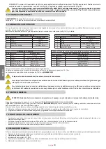
1_   Lock the release lever  by rotating it downward.

2_   Turn 90° the release key and remove it.

3_   Close the protection cover.

4_   Power up the system and perform some movements in order to check the correct restoring of every function.

  10. USE

It is expressly 

forbidden to use the device for any other purposes or under any other circumstances other than those mentioned. The 

electronic control unit 

(which must feature an electric clutch) allows the following functions to be selected:

automatic : a command impulse opens and closes the gate; 

semiautomatic : a command impulse opens or closes the gate.

In the event of a power failure, the gate may be moved manually by activating the “

manual release” device. The model ARM2000BI can be pow-

ered by a backup battery and is able to perform at least 15 complete cycles (open and close) with a fully charged battery.

This is an electrically powered automatic device and should therefore be used with care. In particular: 

•   do not touch with wet hands and/or wet or bare feet;

•   disconnect the power supply before opening the control box and/or the actuator;

•   do not pull the plug out by its cable;

•   do not touch the motor unless you are certain it is cool;

•   only operate the gate when it is completely visible;

•   do not approach the gate while it is moving;

•   do not allow children or animals to play near the gate;

•   do not allow children or  disabled people to use the remote control or other operating devices;

•   carry out routine maintenance;

•   in the case of a fault, disconnect the power supply and only move the gate if it is possible and safe to do so. Do not touch the gate and call in 

an authorised technician.

  11. MAINTENANCE

To ensure trouble-free operation and a constant safety level, an overall check of the system should be carried out every 6 months.

A form for recording operations has been included in the “User Guide” booklet.

ATTENTION: no one, except a trained gate system technician, may use the automatic system during maintenance.

Switch off the mains power supply to eliminate the risk of electrocution. If the power supply must be left on for certain operations, each control 

device should be checked or disabled (remote controls, push buttons, etc.) except for the one used by the trained gate system technician.

The ARM2000IS / ARM2000BI gate operators need very little maintenance. However, as the gate must be in good working order for them to work 

properly, the operations required to keep it in perfect condition are described below.

Routine maintenance

Each of the following operations must be carried out every 6 months for domestic use (approx. 3000 work cycles) and every 2 months for inten-

sive use such as apartment blocks (always 3000 work cycles).

WARNING: In the event installation is to take place in areas exposed to a great deal of sea spray and/or sand (maritime re-

gions, desert zones, etc.), maintenance will need to be performed at shorter intervals, every 2/3 months.

Gate:

-  lubricate and grease hinges and pivot points.

Automation system:

-   check that safety devices (photocells, safety edges, etc.) work according to the manufacturer’s instructions;

-   grease the worm screw from underneath the actuator; TAU srl recommends using the complex lithium soap grease, Code 

M-OILG0NY640M.

-   use a tester for lead-acid batteries to check whether the battery is charged; if it needs replacing use an original battery and recycle the old 

one in compliance with current legislation (TAU recommends using FIAMM batteries).

Extraordinary maintenance or breakage

If major work on electromechanical parts must be carried out, the faulty component should be removed and repaired in the workshop by the 

manufacturer or other authorised technicians.

Keep all the documents concerning the system inside or  near the control unit.

 12. SPECIAL APPLICATIONS

There is no special application other than the described use.

  13. NOISE LEVELS

Airborne noise generated by the gear-motor in normal operating conditions is constant and does not exceed 70 dB.

  14. GUARANTEE: GENERAL CONDITIONS

TAU guarantees this product for a period of 24 months from the date of purchase (as proved by the sales document, receipt or invoice).

This guarantee covers the repair or replacement at TAU’s expense (ex-works TAU: packing and transport at the customer’s expense) of parts that 

TAU recognises as being faulty as regards workmanship or materials.

For visits to the customer’s facilities, also during the guarantee period, a “Call-out fee” will be charged for travelling expenses and labour costs.

The guarantee does not cover the following cases:

ENGLISH

Summary of Contents for ARM 3000 Series

Page 1: ... USO E MANUTENZIONE USE AND MAINTENANCE MANUAL BEDIENUNGS UND WARTUNGSANLEITUNG MANUEL D EMPLOI ET D ENTRETIEN MANUAL DE USO Y MANTENIMIENTO ARM 2000 Series D_MNL0ARM2000 23 11 2020 Rev 34 IT Istruzioni originali ...

Page 2: ... IS 506 ARM3000 803 ARM2000BI BR IS 913 ARM3000 907 3 ARM2000BI BR IS IF IFC 1016 7 ARM3000 122 5 99 fig 1 1 2 6 5 3 4 7 8 9 10 fig 2A 350 mm max 50 mm ARM2000IF fig 2B 340 mm max 50 mm max 50 mm ARM2000IFC 1 1 ARM 2000 SERIES ...

Page 3: ...m c 2x0 5 mm 2x0 5 mm d 4x0 5 mm 4x0 5 mm e 3x0 5 mm 3x0 5 mm f 2x1 mm 1RG58 2x1 mm 1RG58 ARM 2000 SERIES sezione di 2 5 mm2 obbligatoria per i motori in c c 2 5 mm2 section mandatory for DC motors 2 5 mm2 Querschnitt für Gleichstrommotoren obligatorisch Section 2 5 mm2 obligatoire pour les moteurs DC Sección de 2 5 mm2 obligatoria para motores DC Seção de 2 5 mm2 obrigatória para motores de corre...

Page 4: ...4 1 1 2 O R fig 7 fig 8 fig 7A fig 10 10 mm 1 2 fig 9A fig 9B 1 fig 11 fig 12A fig 12B ARM 2000 SERIES fig 6 M5 4Nm max ...

Page 5: ...Negativo encoder Negativo encoder Positivo encoder Encoder positive Pluspol Encoder Positif encoder Positivo encoder Positivo encoder Segnale encoder Encoder signal Encodersignal Signal encodeur Señal encoder Sinal encoder Negativo motore Motor negative Minuspol Motor Négatif moteur Negativo motor Negativo motor Positivo motore Motor Positive Pluspol Motor Positif moteur Positivo motor Positivo mo...

Page 6: ... incorrecta do equipamento ou a não conformidade com a norma vigente Ver Directiva de Máquinas The data described in this handbook are purely a guide TAU reserves the right to change them in any moment The manufacturer reserves the right to modify or improve products without prior notice Any inaccuracies or errors found in this handbook will be corrected in the next edition When opening the packin...

Page 7: ...letamente aperto Y L Utente utilizzatore deve astenersi da qualsiasi tentativo di riparazione o d intervento diretto e rivolgersi solo a personale qualificato Z Tutto quello che non è previsto espressamente in queste istruzioni non è permesso Consigliamo di riporre tutta la documentazione relativa all impianto all interno o nelle immediate vicinanze della centralina Italiano IMPORTANT NOTICE FOR T...

Page 8: ...nstallation genau lesen da sie wichtige Hinweise mit Bezug auf Sicherheit Installation Bedienung und Wartung liefern Eine falsche Installation oder ein fehlerhafter Betrieb des Produktes können zu schwerwiegenden Personenschäden führen B Das Verpackungsmaterial Kunststoff Styropor usw sollte nicht in Reichweite von Kindern aufbewahrt werden da es eine potentielle Gefahrenquelle darstellt C Die Anl...

Page 9: ...AIS DE SEGURANÇA A Leia atentamente as instruções antes de proceder à instalação na medida em que estas fornecem indicações importantes relativas à segurança à instalação à utilização e à manutenção Uma instalação ou utilização incorrectas podem traduzir se em sérios riscos para as pessoas B Os materiais da embalagem plástico poliestireno etc não devem ser deixados ao alcance das crianças na medid...

Page 10: ...locidad motor en vacío Velocidade do motor em vazio 1850 rpm 1000 rpm Rapportodiriduzione Reductionratio Untersetzungsverhältnis Rapport de réduction Relación de reducción Relação de transmissão 1 24 Lunghezza max anta Max length of leaf Max Flügellänge Longueur max battant Longitud máx hoja Largura máx da folha 3000 mm Corsa utile Useful travel Arbeitshub Course utile Carrera útil Curso útil 396 ...

Page 11: ...TÀ SI RIDUCONO DEL 30 CA N B WHEN THE SYSTEM IS IN THE 12 V DC MODE AND IS POWERED BY THE BATTERY ONLY IN THE EVENT OF A POWER FAILURE OR WHEN USED IN CONJUNCTION WITH A PHOTOVOLTAIC PANEL THE GEAR MOTOR S OUTPUT POWER AND SPEED IS REDUCED BY APPROXIMATELY 30 ANMERKUNG WENN DAS 12 VDC SYSTEM NUR ÜBER BATTERIE GESPEIST IST BEI STROMAUSFALL ODER IN KOMBINATION MIT EINEM PHOTOVOLTAICPANEEL VERRINGERN...

Page 12: ... Attuatore 4x1 5 mm 1 Attuatore 2x2 5 mm 3x0 5 mm 2 Centrale di comando 3x1 5 mm alimentazione 2 Centrale di comando 3x1 5 mm alimentazione 3 Supporto centrale di comando 3 Supporto centrale di comando 4 Fotocellula TX 2x0 5 mm 4 Fotocellula TX 2x0 5 mm 5 Fotocellula RX 4x0 5 mm 5 Fotocellula RX 4x0 5 mm 6 Selettore a chiave 3x0 5 mm 6 Selettore a chiave 3x0 5 mm 7 Lampeggiante ed antenna 2x1 mm 1...

Page 13: ...guenza 3_ Verificare che l attacco anteriore 1 fig 9A si trovi nella posizione indicata in fig 9A a 10 mm ca dal tappo 2 fig 9A Nel caso questo non si veri fichi per portare in posizione l attacco è necessario alimentare momentaneamente l attuatore ATTENZIONE È possibile movimentare manualmente l attuatore solo ed esclusivamente se installato sul cancello ed in posizione sbloccata vedi par SBLOCCO...

Page 14: ... elettronico Nel caso in cui vengano installati pulsanti di comando o spie di segnalazione all interno di abitazioni o di edifici che distano parecchi metri dalla centrale stessa è consigliabile disaccoppiare il segnale tramite relay onde evitare disturbi indotti MESSA IN FUNZIONE ATTENZIONE Prima di effettuare qualsiasi intervento sull impianto o sull attuatore togliere l alimentazione elettrica ...

Page 15: ...uno eseguire con cadenza semestrale un controllo generale dell impianto Nel fascicolo Guida per l Utente è stato predisposto un modulo per la registrazione degli interventi da farsi regolarmente ATTENZIONE nessuna persona ad eccezione del manutentore che deve essere un tecnico specializzato deve poter comanda re l automatismo durante la manutenzione Si raccomanda perciò di togliere l alimentazione...

Page 16: ...U S r l Indirizzo Via E Fermi 43 36066 Sandrigo Vi ITALIA Dichiara sotto la propria responsabilità che il prodotto Attuatore elettromeccanico realizzato per il movimento automatico di Cancelli a Battente per uso in ambiente Residenziale Condominiale completo di Modello ARM2000 Tipo ARM2000BI ARM2000BR ARM2000IS ARM2000IF ARM2000IFC Numero di serie VEDI ETICHETTA ARGENTATA Denominazione commerciale...

Page 17: ...nd BR Pos Description Cables Pos Description Cables 1 Operator 4x1 5 mm 1 Operator 2x2 5 mm 3x0 5 mm 2 Control unit 3x1 5 mm power supply 2 Control unit 3x1 5 mm power supply 3 Control unit support 3 Control unit support 4 TX photocells 4x0 5 mm 4 TX photocells 4x0 5 mm 5 RX photocells 2x0 5 mm 5 RX photocells 2x0 5 mm 6 Key switch 3x0 5 mm 6 Key switch 3x0 5 mm 7 Flashing light and aerial 2x1 mm ...

Page 18: ...a distance of approx 10 mm from the cap If this is not the case in order to adjust the position of the lead screw carrier block the gate operator should be momentarily powered ATTENTION The operator can be moved by hand only if it is installed on the gate and in released position see MANUAL RELEASE 4_ check the distance C pic 4 5_ assemble the leaf bracket as shown in pic 10 6_ rest the bracket th...

Page 19: ...l unit it is advisable to decouple the signal by means of a relay in order to avoid induced interference 6 START UP ATTENTION Cut power before any job on the operator or the controller Carefully observe points 10 11 12 13 and 14 of the SAFETY GENERAL RULES With reference to the indications in pic 3 and in the table see INSTALLATION set the ducts and carry out the electrical connections of the cont...

Page 20: ... push buttons etc except for the one used by the trained gate system technician The ARM2000IS ARM2000BI gate operators need very little maintenance However as the gate must be in good working order for them to work properly the operations required to keep it in perfect condition are described below Routine maintenance Each of the following operations must be carried out every 6 months for domestic...

Page 21: ...eclaration of conformity with the provisions of Directive 2006 42 EC The following standards and technical specifications are applied EN 61000 6 2 EN 61000 6 3 EN 60335 1 EN 300 220 2 V2 4 1 EN 12453 2000 EN 12445 2000 EN 60335 2 103 The manufacturer undertakes to provide on sufficiently motivated request by national authorities all information pertinent to the quasi machinery Sandrigo 21 07 2017 ...

Page 22: ... Elektronische Steuerung 3x1 5 mm Motorleitung 2 Elektronische Steuerung 3x1 5 mm Motorleitung 3 Steuerung Standsäule 3 Steuerung Standsäule 4 Lichtschranke TX 4x0 5 mm 4 Lichtschranke TX 4x0 5 mm 5 Lichtschranke RX 2x0 5 mm 5 Lichtschranke RX 2x0 5 mm 6 Schlüsselschalter 3x0 5 mm 6 Schlüsselschalter 3x0 5 mm 7 Blinkleuchte und Antenne 2x1 mm 1RG58 7 Blinkleuchte und Antenne 2x1 mm 1RG58 8 Mechani...

Page 23: ...rdere Toranschlussbügel 1 Abb 9A in der in Abb 9A gezeigten Stellung befindet ca 10 mm von der Haube 2 Abb 9A Andernfalls Torantrieb kurz wieder einschalten um den Toranschlussbügel in Position zu bringen ACHTUNG Der Antrieb kann nur dann mit der Hand bewegt werden wenn er auf dem Tor eingebaut ist und sich in entriegelter Position befindet siehe Abschnitt MANUELLE ENTRIEGELUNG 4_ Das Maß C überpr...

Page 24: ...l der Zusatzvorrichtungen in den Kabelkanälen zu verlegen in denen andere Kabel vorhanden sind die große Lasten oder Lampen mit elektronischem Starter speisen Falls Tasten oder Kontrollleuchten in Wohnungen oder Gebäuden installiert werden die mehrere Meter vom Steuergerät entfernt sind empfehlen wir die Abkopplung des Signals über ein Relais um Störungen zu vermeiden 6 INBETRIEBNAHME ACHTUNG Vor ...

Page 25: ... allgemeine Kontrolle der Anlage vorzunehmen Im Heft Betriebsanleitung ist ein Formular für die Aufzeichnung der Arbeiten enthalten ACHTUNG niemand mit Ausnahme des Wartungsmannes der ein Fachtechniker sein muss ist befugt die Automatisierung während der Wartung zu steuern Es wird daher empfohlen die Netzstromversorgung abzuschalten wodurch auch die Stromschlaggefahr vermieden wird Falls die Verso...

Page 26: ...g dass das Produkt Elektromechanischer Antrieb für die automatische Bewegung von Drehtore für eine Anwendung Privat Gewerbe Einschließlich Modell ARM2000 Typ ARM2000BI ARM2000BR ARM2000IS ARM2000IF ARM2000IFC Seriennummer SIEHE SILBERETIKETTE Handelsbezeichnung DREHTORANTRIEB FÜR PRIVAT UND GEWERBE ausgeführt wurde um in einen Verschluss integriert zu werden Drehtore oder um mit anderen Vorrichtun...

Page 27: ... Description Câbles Pos Description Câbles 1 Opérateur 4x1 5 mm 1 Opérateur 2x2 5 mm 3x0 5 mm 2 Logique de commande 3x1 5 mm alimentation 2 Logique de commande 3x1 5 mm alimentation 3 Colonne équipant le coffret commande 3 Colonne équipant le coffret commande 4 Photocellules TX 4x0 5 mm 4 Photocellules TX 4x0 5 mm 5 Photocellules RX 2x0 5 mm 5 Photocellules RX 2x0 5 mm 6 Sélecteur à clé 3x0 5 mm 6...

Page 28: ...ier le réglage 3_ Vérifier que la fixation avant 1 fig 9A se trouve dans la position indiquée sur la fig 9A à 10 mm environ de la cache 2 fig 9A Si ce n est pas le cas pour positionner correctement la fixation il faut alimenter momentanément le vérin ATTENTION on peut actionner l opérateur manuellement uniquement et exclusivement s il est installé sur le portail et en position débloquée voir par D...

Page 29: ... les lampes par starter électronique Au cas où il faut installer des boutons de commande ou de voyants de signalisation dans les maisons ou les bâtiments qui sont situés à quelques mètres de la centrale de commande il est conseillé de découpler le signal au moyen de relais pour éviter les bruits induits 6 MISE EN FONCTION ATTENTION Couper le courant avant toute intervention sur l installation ou s...

Page 30: ...nement correct et un niveau de sécurité constant effectuer tous les six mois un contrôle général de l installation Dans le livret Guide Usager se trouve un formulaire pour l enregistrement des interventions ATTENTION personne à l exception de la personne chargée de la maintenance qui doit être un technicien spécialisé doit pouvoir commander l automatisme pendant la maintenance Nous recommandons pa...

Page 31: ...et adresse de la personne autorisée à constituer la documentation technique pertinente Loris Virgilio Danieli via E Fermi 43 36066 Sandrigo Vi Italy 13 NIVEAU SONORE Le bruit aérien produit par l opérateur dans des conditions normales d utilisation est constant et ne dépasse pas 70 dB 14 GARANTIE CONDITIONS GÉNÉRALES La garantie TAU a une durée de 24 mois à compter de la date d achat des produits ...

Page 32: ...Accionador 2x2 5 mm 3x0 5 mm 2 Cuadro de maniobras 3x1 5 mm alimentación 2 Cuadro de maniobras 3x1 5 mm alimentación 3 Columna para cuadro de maniobras 3 Columna para cuadro de maniobras 4 Foto células TX 4x0 5 mm 4 Foto células TX 4x0 5 mm 5 Foto células RX 2x0 5 mm 5 Foto células RX 2x0 5 mm 6 Interruptor de llave 3x0 5 mm 6 Interruptor de llave 3x0 5 mm 7 Lámpara y antena 2x1 mm 1RG58 7 Lámpara...

Page 33: ...ue la tuerca corredera 1 fig 9A se encuentre en la posición indicada en la fig 9A a 10 mm aprox del tapón 2 fig 9A Si no es así para colocar en la posición adecuada la tuerca corredera es necesario alimentar momentáneamente el actuador ATENCIÓN Se puede mover manualmente el operador sólo y exclusivamente si está instalado en la puerta y en posición desbloqueada véase párrafo DESBLOQUEO MANUAL 4_ C...

Page 34: ...maniobras si es externo cerca de los motores No coloque los cables de los dispositivos auxiliares dentro de tuberías donde haya otros cables que alimenten grandes cargas o lámparas con arrancador electrónico Si se instalan pulsadores de mando o indicadores luminosos dentro de habitaciones o de edificios que estén a varios metros de distancia del cuadro de maniobras se aconseja desacoplar la señal ...

Page 35: ...ontrol general del equipo En la Guía usuario se ha preparado un módulo para anotar las intervenciones ATENCIÓN ninguna persona salvo el técnico encargado del mantenimiento que debe ser un técnico especializado debe po der accionar la automatización durante el mantenimiento Por lo tanto se recomienda desconectar el aparato de la red evitando el peligro de sacudidas eléctricas En cambio si fuera nec...

Page 36: ... la Directiva Europea 2006 42 CE Adj II B Fabricante TAU S r l Dirección Via E Fermi 43 36066 Sandrigo Vi ITALY Declara bajo su propia responsabilidad que el producto Actuador electromecánico fabricado para el movimiento automático de Puertas Batientes para uso en ambiente Residencial Comunidades equipado con Modelo ARM2000 Tipo ARM2000BI ARM2000BR ARM2000IS ARM2000IF ARM2000IFC Número de serie VÉ...

Page 37: ...stalação standard com ARM2000BI e BR Nº Descrição Cabos Nº Descrição Cabos 1 Motorredutor 4x1 5 mm 1 Motorredutor 2x2 5 mm 3x0 5 mm 2 Unidade de controlo 3x1 5 mm alimentação 2 Unidade de controlo 3x1 5 mm alimentação 3 Suporte em coluna para unidade de controlo 3 Suporte em coluna para unidade de controlo 4 Fotocélula TX 2x0 5 mm 4 Fotocélula TX 2x0 5 mm 5 Fotocélula RX 4x0 5 mm 5 Fotocélula RX 4...

Page 38: ...strada na fig 9A a cerca de 10 mm do topo 2 fig 9A Caso não esteja na posição pretendida o motorredutor deve ser ligado momentaneamente para colocar o elemento na posição desejada ATENÇÃO É possível movimentar manualmente o motorredutor única e exclusivamente se instalado no portão e na posição de desbloque ado ver parágrafo DESBLOQUEIO MANUAL 4_ VVerificar o valor da cota C 5_ Montar o suporte de...

Page 39: ...que os cabos dos dispositivos auxiliares estejam posicionados dentro de tubos onde existam outros cabos que suportem grandes cargas ou lâmpadas com arranque electrónico Se forem instalados botões de comando ou luzes de sinalização dentro de casas ou edifícios a vários metros de distância da unidade de controlo é aconselhável desacoplar o sinal por meio de um relé para evitar distúrbios induzidos 6...

Page 40: ...alimentação da rede eléctrica e movimentar o portão manualmente somente quando for possível fazê lo em segurança Não efectuar qualquer tipo intervenção e chamar um técnico qualificado 11 MANUTENÇÃO A fim de garantir o correcto funcionamento e um nível de segurança constante ao longo do tempo é aconselhável realizar uma inspecção geral ao sistema a cada seis meses No documento Guia do Utilizador en...

Page 41: ...uase máquinas Sandrigo 27 06 2018 O Representante legal _________________________________________ Loris Virgilio Danieli Nome e endereço da pessoa autorizada a constituir a documentação técnica pertinente Loris Virgilio Danieli via E Fermi 43 36066 Sandrigo Vi Italia Não existem aplicações especiais além das aplicações descritas 13 NÍVEL DE RUÍDO O ruído produzido pelo motorredutor em condições no...

Page 42: ...42 ...

Page 43: ...43 ...

Page 44: ...TORIAL How to unlock a swing gate auto mated with Tau operators FRANÇAIS VIDEO TUTORIAL Comment déverrouillage du portail battant automatisé avec les moteurs Tau Via Enrico Fermi 43 36066 Sandrigo VI Italy Tel 39 0444 750190 Fax 39 0444 750376 info tauitalia com www tauitalia com ...

Reviews: