E.
Remove 10 screws from the back cover.
F.
Remove 1 screw from the back cover, and then take back cover apart from the LCD
TV
G.
Remove 4 screws from the VESA wall-mounting bracket.
H.
Remove the shield of power box.
H.’
Remove 2 screws, and then disconnect 3 wire assemblies from power box.
H.”
Remove 1 screw from shield of main board, and 4 hexagonal screws from the DVI
and D-Sub connectors.
- 11-
G
G
H
H’
H’’
Summary of Contents for V32FLBB
Page 10: ...5 Remote Control 5 1 Remote Control 8 VIDEO SWAP...
Page 15: ...13 K Take Panel Bracket apart from the Front Cover...
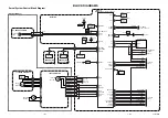
Page 16: ...14 7 Block Diagram...
Page 26: ...11 Circuit Diagram 11 1 Main Board PWB 0713 24...
Page 27: ...25...
Page 28: ...26...
Page 29: ...27...
Page 30: ...28...
Page 31: ...29...
Page 32: ...30...
Page 33: ...31...
Page 34: ...32...
Page 35: ...33...
Page 36: ...34...
Page 37: ...35...
Page 38: ...36...
Page 39: ...37...
Page 40: ...38...
Page 41: ...39...
Page 42: ...40...
Page 43: ...11 2 Tuner I O Board PWB 0733 41...
Page 44: ...42...
Page 45: ...11 3 Interface Key IR Board PWB 0768 43...
Page 47: ...12 PCB Layout 12 1 Main PCB PWB 0713 Front Side 45...
Page 48: ...Rear side 46...
Page 49: ...12 2 Tuner PCB I O PCB PWB 0733 Front Side Rear side 47...
Page 50: ...12 3 Interface Key IR PCB PWB 0768 Front Side Rear side 48...
Page 53: ...14 Mechanical Disassembly 51...


