background image

 23

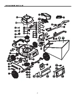
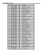
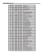
REPLACEMENT PARTS LIST

Item No.

Part No.

Qty

Description

33-4

3340138

1

33-5

3422139

2

34

3410238

1

35

31102222

1

36

3220137

3

37

33302222

1

38

1

38-1

33401222

1

38-2

3290506

1

38-3

31103222

1

38-4

34110227

1

39

3411135

2

40

31104227

1

40-1

3331338

1

40-2

34902227

1

41

33302227

1

42

31102227

1

42-1

33301227

1

42-2

34901227

1

43

31103227

1

44

3410835

4

45

3220436

2

46

925123

1

46-1

3220136

2

46-2

3330637

1

46-3

3220537

2

46-4

3320338

1

46-5

3340237

1

46-6

3410338

1

47

3410438

1

48

3410137

1

49

3221137

2

50

3410403

1

51

3220105

2

52

3410290-1

1

53

3331437

1

54

3690137

1

55

3220511

1

56

3220850

2

57

3220951

2

58

3220439

2

59

3290105

1

60

3290706

1

Rear metal gate spring
rubber washer
Mulch plug for 20"Mower
20" rear wheel axle
Bolt
Rear R.wheel height adj. bracket
Height adjustment handle assy.
Height adjustment spring
E-Clip
Height adjustment threaded bar
Height adjustment shifter handle
Cord guide
Grass bag assembly
Grass bag frame
Task Force Grass Bag
20"Lower handle assembly
20"Upperhandle assembly
20"Upper handle (bar only)
Foam grip for upper handle
Power switch assembly
Knob for handle bars
Bolt (Used for knob on handles)
Side discharge door assembly
Bolt for side discharge bracket
Side discharge door bracket
Lock nut - for side discharge door
Pin - for side discharge door
Spring - for side discharge door
Side discharge door with label
Side discharge chute
Cable clamp base
Machine Screw
Cable clamp top
Self tapping screw for wire loom
Rectifier support bracket - plastic
Rectifier heat sync.
Rectifier and bracket assy.
Machine Screw
Machine Screw
Self tapping screw ST 5X16-C
Lock nut - used with rectifier plate
Nut - used with rectifier plate
Washer - used with rectifier plate

Summary of Contents for 25043

Page 1: ... BEFORE USE CAUTION FOR YOUR SAFETY NOTICE On the nameplate of your machine you will find MFG date code of your unit Please record these numbers on this manual cover for future service reference MFG DATE ________ PURCHASE DATE _________ Questions problems missing parts Before returning to your retailer call our customer service department at 1 866 456 8934 8 00 a m 6 00 p m EST Monday Thursday 8 0...

Page 2: ...RPM Cutting path 20 in Height adjustments 1 1 2 in 3 3 4 in Weight 49 lbs 22 3 kg 20 IN ELECTRIC LAWN MOWER Product Specifications 2 Safety Information 3 Know your lawn mower 6 Assembling your lawn mower 7 Operating your lawn mower 14 Service 18 Troubleshooting 19 Warranty 20 Replacement parts list 21 ...

Page 3: ...ON 1 Read understand and follow all instructions on the machine and in the manual before attempting to assemble and operate 2 Keep this manual in a safe place for future and regular reference Befamiliarwith allcontrols and their proper operation Know how to stop the machine and disengage the controls quickly 3 Avoid Dangerous Environment Don t use lawn mowers in damp or wet locations 4 Don t Use I...

Page 4: ...ect extension cords periodically and replace if damaged Keep handles dry clean and free from oil and grease 16 Keep guards in place and in working order 17 Keep blades sharp 18 Keep hands and feet away from cutting area 19 Objects struck by the lawn mower blade can cause severe injuries to persons The lawn should always be carefully examined and cleared of all objects prior to each mowing 20 If la...

Page 5: ... proper wall outlet Do not change the equipment plug extension cord receptacle or extension cord plug in any way Extension Cord 1 Warning To prevent electric shock use only with an extension cord suitable for outdoor use such as SW A SOW A STW A STOW A SJW A SJOW A SJTW A or SJTOW A 2 Make sure your extension cord set is in good condition When using an extension cord be sure to use one heavy enoug...

Page 6: ...n of various controls and adjustments Save this manual for future reference ATTACHING EXTENSION CORD TO MOWER The cord restraint is located on the back of the upper handle and when used properly helps to protect the motor blade control assembly and extension Power switch assembly Upper handle Lower Grass catcher bag handle Motor housing Side discharge chute Side discharge cover Height adjustment l...

Page 7: ...d lower handles for shipping purposes 2 Pull up and back on the upper handle to raise the handle into the operating position Make certain the lower handle is seated securely into the handle mounting bracket see Fig 1 3 Align the holes 3 between the upper handle 1 and lower 3 handles Insert the bolts 4 and tighten them with the wing nuts 5 provided 4 Secure the lower handle to the bracket with the ...

Page 8: ...POWER CORD AND WAIT FOR BLADE TO COME TO A COMPLETE STOP 2 Lift the chute cover 1 3 While holding up the cover 1 place the grass catcher bag hanger hooks 2 into the opening on the chute cover 1 to allow the hanger hooks to attach to the rod 4 which secures the chute cover 1 2 ...

Page 9: ...teps 2 To pull open the mulch cover 1 align the discharge chute arrows with the positioning arrows on the mower deck and slide the discharge chute 2 as shown 3 Position the chute until the chute hooks are trapped under the deck hooks and release the chute and mulch plug 1 UNPLUG THE POWER CORD AND WAIT FOR BLADE TO COME TO A COMPLETE STOP 1 2 2 1 ASSEMBLING YOUR LAWN MOWER 9 ...

Page 10: ...OF THE MULCH PLUG 2 To remove the mulch plug lift the chute cover 1 and pull out on the handle 3 The mulch plug 2 is inserted on an angle so it will require some force when removing 2 1 1 UNPLUG THE POWER CORD AND WAIT FOR BLADE TO COME TO A COMPLETE STOP ...

Page 11: ... you can grasp it with your other handle Pull the lever back to turn the unit on and hold it against the mower handle to keep it running To turn the mower off just release the lever Caution never attempt to override the operation of this switch 1 Push the safety tab out to expose the lever 2 Pull the lever up to start the mower 3 Release the lever to stop the mower ...

Page 12: ...ove to desired position This sets all wheels to the same position 2 To raise the height pull the height adjustment lever from the current stop position towards the back of the mower 3 To lower the height pull the height adjustment lever from the current stop position towards the front of the mower HIGH LOW 1 ...

Page 13: ...SEMBLING YOUR LAWN MOWER 13 ADJUST THE UPPER HANDLE HEIGHT 1 Loosen the upper handle knob 2 Adjust the handle to the most comfortable of the 3 positions 3 Tighten the upper handle knob as tight as you can ...

Page 14: ... Do not mow on inclines with a slope in excess of 15 or a rise of approximately 2 1 2 every 10 Operate mower across the face of slopes never up or down slopes SLOPE GAUGE Use this page as a guide to determine slopes where you may not operate safely MOWING TIPS NOTE A sharp blade will greatly increase the performance of your mower especially in high grass conditions Be sure to check the blade and s...

Page 15: ...ass as it tends to stick to the underside of the deck preventing proper mulching of grass clippings New or thick grass may require a narrower cut The ground speed should be adjusted to the condition of the lawn If mowing has been delayed and the grass has been allowed to grow in excess of 4 mow twice to reduce the grass height to 3 3 4 maximum 4 Walk at a good steady pace Overlap your rows Don t l...

Page 16: ...ove the blade 4 To loosen the nut turn CLOCKWISE and to tighten turn COUNTER CLOCKWISE This is a reverse rotation nut 4 Remove blade nut 1 square washer 2 insulator washer 3 and blade 5 To re assemble first position the blade with the cutting edges to wards the ground Assemble the blade nut square washer insulator washer as showing Using a 15mm socket with a torque wrench turn the blade nut COUNTE...

Page 17: ...ucted in previous section Inspect and replace sharpen blade if required Refer to the Maintenance section Store mower in a dry clean area Do not store next to corrosive materials such as fertilizer and rock salt Wipe extension cord to remove any foreign substances such as oil or stains Replace extension cord if cut or damaged in any way Wind cord in a series of equal loops to prevent it from tangli...

Page 18: ... mounting bolts at frequent intervals for proper tightness Also visually inspect blade for damage e g bent cracked and worn 8 Maintain your mower with care Keep mower blade sharp and clean for best and safe performance Mower blades are sharp and can cut wrap the blades or wear gloves and use extra caution when servicing them 9 Keep all nuts bolts and screws tight to be sure the equipment is in saf...

Page 19: ...grass unevenly Lawn is rough or uneven Cutting height not set properly Move the wheels to a higher position All wheels must be placed in the same cutting height for the mower to cut evenly Mower not mulching properly Wet grass clippings stick to the underside of the deck Wait until the grass dries before mowing Hard to push High grass or cutting height too low Rear of mower housing and blade dragg...

Page 20: ...accessories and or attachments not specifically recommended Repairs necessary because of operator abuse or negligence or the failure to install operate maintain and store the product according to the instructions in the owner s manual Damage caused by cold heat rain excessive humidity corrosive environments and materials or other contaminants Expendable items that become worn during normal use Cos...

Page 21: ...21 REPLACEMENT PARTS LIST ...

Page 22: ...s Motor cover only TF Motor cover seal TF Electrical bridge screw Electrical bridge KBPC2504 Electrical bridge heat sync 12A motor assembly Front bumper Lock Nut M6 20 Mower deck Task Force Nut M5 Machine Screw M5 x 10 20 front wheel axle assy Front wheel spacer 7 Front wheel Washer for wheels Wheel attaching cir clip Task Force wheel center cap Link bar for 20 Mower Label bracket for link bar Spr...

Page 23: ...r R wheel height adj bracket Height adjustment handle assy Height adjustment spring E Clip Height adjustment threaded bar Height adjustment shifter handle Cord guide Grass bag assembly Grass bag frame Task Force Grass Bag 20 Lower handle assembly 20 Upperhandle assembly 20 Upper handle bar only Foam grip for upper handle Power switch assembly Knob for handle bars Bolt Used for knob on handles Side...

Reviews: