©Copyright Task Force Tips, Inc. 2002 - 2015
LIN-035 June 16, 2015 Rev15
22
9.0 COLOR CODED VALVE HANDLE AND PISTOL GRIP
The TFT nozzle with lever type valve handles are supplied with black valve handle covers and pistol grips. The handle covers and
pistol grips are available from TFT in various colors for those departments wishing to color code the nozzle to the discharge controls.
A colored handle cover set will be sent upon receipt of the warranty card by TFT. Your department’s name can also be engraved on
the covers (see warranty card for more information).
Handle covers are replaceable by removing the four screws that hold the handle covers in place. Use a 3/32” Allen wrench when
replacing screws. Pistol grip is replaceable by following TFT instruction sheet LTT-108 for standard grips or LTT-115 for Trigger
Controlled Valves.
For standardization NFPA 1901 (A-4-9.3) recommends the following color code scheme:
Preconnect #1 or Bumper Jump Line
Preconnect or discharge #2
Preconnect or discharge #3
Preconnect or discharge #4
Preconnect or discharge #5
Preconnect or discharge #6
Preconnect or discharge #7
Foam Lines
Orange
Red
Yellow
White
Blue
Black
Green
Red w/ White border (Red/White)
Other Colors Available:
• Gray
• Pink
• Purple
• Tan
9.1 IMPULSE TRIGGER VALVE SYSTEM NOZZLE COLORED PISTOL GRIPS
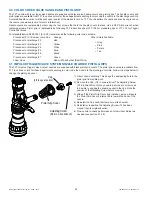
The TFT Impulse Trigger Valve System nozzles are supplied with black pistol grip covers. The pistol grip covers are available from
TFT in various colors for those departments wishing to color code the nozzle to the discharge controls. Follow the steps below to
change the pistol grip cover.
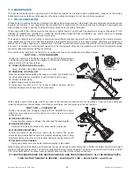
Pistol Grip Cover
Cap
(1/2 in square drive)
Adjusting Screw
(3/16 in Allen Wrench)
1) Orient nozzle vertically. This keeps the dampening fl uid in the
pistol grip from spilling out.
2) Remove the Cap. (1/2 in square drive) The Adjusting Screw
(3/16 in Allen Wrench) may need to be turned in or removed
to be able to engage the square pocket in the cap. Note the
position of the Adjusting Screw before moving it.
3) Slide off the Pistol Grip Cover and install a new one. Be sure
the Pistol Grip Cover’s internal rib is toward the back of the
nozzle.
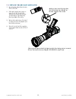
4) Reinstall the Cap until it bottoms out on its shoulder.
5) Reinstall or reposition the Adjusting Screw if it has been
moved from its original location.
6) Flow nozzle to check performance of slow closer. Adjust as
needed (see section 5.1.5.2).

