background image


21

 
You can also control the input monitor 
settings that will be used when the US-224 
first starts up. You can choose either the last 
settings in effect at the previous system 
shutdown, or any one of the four snapshots.


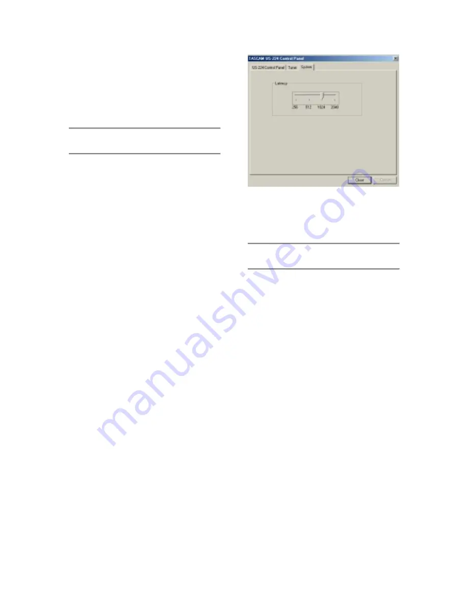
5.2  Buffer Size Adjustment 


The US-224 Control Panel contains a 
second page, tabbed “System”.  On this 
page the buffer size can be adjusted. 


Smaller buffer sizes will result in lower 
latency, but requires a faster system.


About Buffer Sizing: 
 

The US-224 driver temporarily stores input 
and output audio samples in buffers.  Larger 
buffers provide more safety against other 
system activities interrupting the audio and 
producing clicks, pops or other audible 
artifacts.  Smaller buffers provide lower 
latency when using the computer to send 
input audio to output channels in order to 
monitor the input.  The driver lets users 
select which buffer size works best for their 
computer and audio application.  Note: This 
adjustment does not affect the latency of the 
US-224’s hardware input monitor, which is 
always less than an ultra-low 1.5 ms. 
 
To adjust the buffer size, run the US-224 
Control Panel and go to the System tab.  
The Audio Latency slider lets you change 
the buffer size from a minimum of 256 
samples (128 samples on the Mac) to a 
maximum of 2048 samples.  All audio 
programs that use the US-224 must quit 
before a new audio latency setting takes 
effect.  Using Cubase VST at 44.1 kHz 
sampling rate, a 256 sample buffer size 
gives appx. 12 ms of monitoring latency, 
while a 2048 sample buffer gives appx 43 
ms latency.


5.3  The Chromatic Tuner 


Open the US-224’s control panel and select 
the “Tuner” tab. 
 
In the “Input” section, select the US-224 
input channel that you want to tune (A or B). 
 
Play a note and adjust the trim knob for that 
input until the signal is strong, but not 
clipping. 
 
The “Level” meter on the screen should 
display bright green segments without 
lighting the top red segment. 
 
If desired, you can change the Tuning 
Standard in the “Reference” section. 
Normally, the Tuning Standard is set to 440 
cycles per second for a middle “A” note, but 
you can use the up/down arrows to change 
it to a number between 430 and 450 cycles 
per second. 
 
As you play, the detected note will be 
displayed below the Tuning lights (A# or E, 
for example). If the note is sharp, the 
“Sharp” arrow and a Tuning light to the right 
of ‘0’ are bright red; if the note is flat, the 
“Flat” arrow and a Tuning light to the left of 
‘0’ are bright red.  

Illustration 5.02 – System Tab 

Summary of Contents for US-224

Page 1: ...1 TASCAM TEAC Professional Division US 224 Universal Serial Bus Digital Audio Workstation Controller OWNER S MANUAL D000640100A...

Page 2: ...ELLOW must be connected to the terminal in the plug which is marked by the letter E or by the safety earth symbol or coloured GREEN or GREEN and YELLOW The wire which is coloured BLUE must be connecte...

Page 3: ...Article 810 of the National Electrical Code ANSI NFPA 70 provides information with regard to proper grounding of the mast and supporting structure grounding of the lead in wire to an antenna discharge...

Page 4: ...loss TEAC Corporation will in no way be liable for any damages consequential or otherwise caused by such loss of data Microsoft Windows Windows NT and Windows XP are all registered trademarks or trad...

Page 5: ...5 3 The Chromatic Tuner 21 6 Interfacing with your Audio Software 23 6 1 Selecting the US 224 as your Audio Device 23 6 1 1 Audio Control Panel 23 6 1 2 ASIO Control Panel 23 6 1 3 VST Remote 23 6 2...

Page 6: ...dphone output The US 224 also features MIDI Input and Output ports allowing you to send and receive data and MIDI Time Code MTC from your MIDI based keyboards and other devices The US 224 s control su...

Page 7: ...ne Out and Phones Output Levels 8 DATA Wheel 9 NULL Switch and LED 10 Input Monitor Switch and LED 11 Bank Switches and LEDs 12 Transport Controls 13 Locate and Set Switches 14 Channel and Master Fade...

Page 8: ...8 2 2 Rear Panel 18 PHONES jack 19 OUTPUT L R jacks 20 INPUT A and B 21 MIC INPUT A and B 22 Digital In and Out 23 MIDI Out 24 MIDI In 25 USB jack 26 POWER switch 18 19 20 21 22 23 24 25 26...

Page 9: ...heel sends continuous controller information to application In Cubasis functions as a shuttle wheel if no SELECT switch is held down or as PAN control if a channel SELECT switch is pressed and held 9...

Page 10: ...ted indicates mute status of selected channel When SOLO LED is on the associated channel s MUTE LED s indicate solo status when lit SOLO switch toggles between mute and solo status SOLO LED when illum...

Page 11: ...computers Chipsets are also a concern with USB audio We ve found that the most dependable motherboards are ones which utilize Intel based chipsets You can determine your chipset by going into the Devi...

Page 12: ...software cannot be installed If the disc becomes unreadable a charge will be made for its replacement Do not attempt to play the enclosed CD ROM using an audio CD player as this may cause damage to h...

Page 13: ...files will be installed to your hard drive NOTE You may be prompted by a message informing you that the software you are about to install does not have a digital certificate Simply click Continue the...

Page 14: ...menu When prompted to select a serial modem or printer port leave both selections unchecked Click yes and continue OMS will assess all the MIDI ports attached to your computer and build OMS instrument...

Page 15: ...s RAM to 96 128 or even 256 MB will markedly improve performance Consider the addition of a dedicated hard disk for audio preferably one with a high spindle rate over 7200 RPM is recommended for most...

Page 16: ...basis usually once every millisecond This can lead to dropouts clicks pops and other artifacts in your audio We strongly suggest unplugging any non essential USB devices while recording with the US 2...

Page 17: ...below the Input Trim control to the Guitar position Finally digital sources e g CD players DAT s etc may be connected to the S PDIF INPUT The inputs of channels A and B are available as either balance...

Page 18: ...DTRS multitrack or any other machine that accepts time code with your digital audio software for transferring tracks back and forth for editing and processing 4 3 Using the Input Monitoring In digital...

Page 19: ...ntrolled by that track s software gain control which in turn is controlled by the US 428 s channel FADERs the MASTER FADER and the LINE OUT or PHONES OUT level controls The LINE OUT and PHONES level c...

Page 20: ...a view of the US 224 s current settings Clock source Internal or Digital In Sample rate 44100 or 48000 Resolution 24 Bit or 16 Bit Digital input Signal Red no digital input Green digital input active...

Page 21: ...m tab The Audio Latency slider lets you change the buffer size from a minimum of 256 samples 128 samples on the Mac to a maximum of 2048 samples All audio programs that use the US 224 must quit before...

Page 22: ...te is in tune the center 0 light and both the Flat and Sharp arrows are bright green Note The chromatic tuner consumes some CPU bandwidth in your system Therefore when you finish using the tuner we re...

Page 23: ...rol Panel In Cubasis open the Audio Control Panel see illustration 6 01 It s located in the Audio pulldown menu under System Select the ASIO Device pull down menu and select ASIO US 224 Driver If your...

Page 24: ...s VST supports only 16 bit audio If you want to record in 24 bit mode you will need to upgrade to Cubase VST or another application that supports 24 bit audio 6 3 Input Enabling You will need to enabl...

Page 25: ...or FFWD will activate Cubasis transports to Rewind or Fast Forward respectively The DATA Wheel will also act as a shuttle wheel for the transport See section 6 6 for details Cubasis will record audio...

Page 26: ...ols and FADER NULL The BANK SELECT keys page between successive banks of four faders Selecting any of the four faders will control the corresponding channel in the software s internal mixer The US 224...

Page 27: ...enable Direct Monitoring in Cubase VST open the Audio Control Panel In the Monitoring section of the window check ASIO Direct Monitor You also need either Record Enable Type or Tape Type monitoring en...

Page 28: ...ower to the US 224 It is also advisable as with all audio devices that you turn your amplifier or powered monitors off until the program is up and running to avoid audio spikes Once you are certain th...

Page 29: ...red OL LED should only flicker occasionally You can then fine adjust the level with the TRIM knobs for the selected channel s NOTE The SIGNAL and OL LED s do not function with digital input In the cas...

Page 30: ...parameters on a particular channel first press the SELECT key for that channel on the US 224 The selected channel will be highlighted below that channel s fader on the screen Moving the channel fader...

Page 31: ...also important to note that the US 224 is fully functional as a 16 and 24 bit audio interface and 16 channel MIDI interface with virtually all Windows and MacOS compatible applications Even those appl...

Page 32: ...t will send a system beep out the US 224 outputs When you click Input on the left the available input devices appear on the right Click on US 224 to select it as the Sound Manager input device Below i...

Page 33: ...der Sound In you can select the US 224 instead of the Mac s Built in sources You can also do this under the US 224 control panel s System tab There you will find a field labeled Sound Manager Input Yo...

Page 34: ...ia select the Devices tab Under Audio Devices you should see Audio for US 224 Under Midi Devices And Instruments you should see MIDI for US 224 Expand by clicking on the plus sign and you should see U...

Page 35: ...this manual contains some basic FAQ s you will find a much more detailed FAQ document on the US 224 CD ROM The FAQ is also updated on a regular basis so we suggest you check the TASCAM website for the...

Page 36: ...hrough After Touch Keys Channels X X X X Through Pitch Bender X X Through Control Change X X Through Program Change True X X Through System Exclusive X X Through System Common Song Pos Song Sel Tune X...

Page 37: ...will be used to communicate between the host and US 224 In many cases the commands transmitted by the US 224 are identical to those generated by the JL Cooper CS 10 controller In general it is desired...

Page 38: ...down BF 14 7F o Button up BF 14 00 TRANSPORT_STOP o Button down BF 15 7F o Button up BF 15 00 TRANSPORT_PLAY o Button down BF 16 7F o Button up BF 16 00 TRANSPORT_REC o Button down BF 17 7F o Button...

Page 39: ...o move each of the faders to agree with the application s virtual fader levels When the user releases NULL the application sends REC and SELECT LED update messages which will cause them to revert to t...

Page 40: ...anks of four channel strips each The Bank L and Bank R switches let the user quickly shift the control surface to address any bank of four channels There are two LED s adjacent to the Bank L and Bank...

Page 41: ...ATA_WHEEL identical to JL Cooper CS 10 a BF 60 vv vv 2 s complement using 7 data bits Host to US 224 Messages UPDATE_ASN_LED F0 4E UNIT 12 0F STATE F7 where UNIT Transmit as 0 for now STATE is either...

Page 42: ...1 1 x 6 2 cm Weight unit itself 0 85 Kg 1 9 lbs Power Consumption 2W MIC INPUT A B Analog Connector XLR 3 31 1 GND 2 Hot 3 Cold Balanced Input Impedance 2 2k ohm Nominal Input Level TRIM max 54 dBu No...

Page 43: ...min 150 ohm terminated LINE OUTPUT max T H D Better than 0 007 at 1kHz TRIM min 0 dBu input LINE INPUT A B 1 4 Analog INPUT to DIGITAL OUT Frequency Response 20 Hz 20KHz 0 5 dB 1 0 dB TRIM min 4 dBu i...

Page 44: ...44 Printed In Taiwan MA 0631 US 224...

Reviews: