background image

10  

TASCAM US-1800

CAUTION

Handle the enclosed CD-ROM with care. If the disc 


becomes scratched or dirty, your computer may be unable 

to read it and the software cannot be installed. If the 

disc becomes unreadable, a fee will be charged for its 

replacement.
Never attempt to play the enclosed CD-ROM in a 


conventional audio CD player, as the resulting noise may 

damage your speakers or your hearing.

Installing the driver for Windows

NOTE

During driver installation, a warning that “this software 


... has not passed Windows Logo testing“ will appear.  

This message appears when a driver that has not 

received Windows Logo testing is installed. This message 

appears because the drivers for TASCAM products have 

not received Windows Logo testing. We have, however, 

confirmed their proper operation. If this message appears, 

click Continue to proceed with the installation.
During installation, you must connect the unit in step 7. 


You should complete each of these installation steps in 

less than one minute. Installation may fail if you take too 

much time.

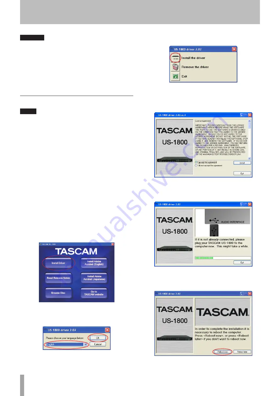
1  Confirm that the unit and the PC are not connected 

by the USB cable.

2  Insert the included driver installation CD-ROM into 

the PC where you will install it.

3  Click the 

Install Driver

 button when the screen 

below appears. (If this screen does not appear 

automatically, find and open the 

Autorun2.exe


program in the 

Autorun

 folder on the driver CD-

ROM.)

4  When the language selection screen (below) 

appears, select the language you prefer and then 

click the 

OK

 button.

5  Click the 

Install the Driver

 button when the screen 

below appears.

6  Read the contents of the License Agreement, 

and select 

I accept the agreement

 if you agree to 

the terms. Next, click the 

Install

 button to start 

installation.

7  When the screen below appears, use the supplied 

USB cable to connect the unit to the PC. Then, turn 

the unit on.

8  When the screen below appears, the installation 

is complete. Click the 

Reboot now

 button to restart 

the PC to use the driver.

3 − Installation

Summary of Contents for US-1800

Page 1: ...US 1800 USB2 0 Audio MIDI Interface D01127720A OWNER S MANUAL...

Page 2: ...em for your records Model number Serial number In North America use only on 120V supply CE Marking Information a Applicable electromagnetic environment E4 b Peak inrush current 0 6 A TO THE USER This...

Page 3: ...cordance with the manufacturer s instructions 8 Do not install near any heat sources such as radiators heat registers stoves or other apparatus including amplifiers that produce heat 9 Do not defeat t...

Page 4: ...Source 12 Digital Output Format 12 Digital Output Channels 12 5 Connections 13 External device connection example 13 USB connections 14 Audio connections 14 Mic 14 Guitar 14 Analog connections with ke...

Page 5: ...and other use WDM for audio control USB 2 0 High speed 480 MHz compatible Cubase LE 5 included A note about computer operation If you are unsure about how to perform basic computer operations appearin...

Page 6: ...places Doing so could degrade the sound quality and or cause malfunctions Places with significant vibrations or that are otherwise unstable Near windows or other places exposed to direct sunlight Nea...

Page 7: ...tandard TRS analog input jacks When the switch is pressed in the corresponding jack functions as an unbalanced guitar input GUITAR When the switch is out the corresponding jack functions as a balanced...

Page 8: ...dBV 10 or 4 dBu 4 NOTE The gain of these jacks cannot be adjusted y LINE OUT BALANCED jacks 1 4 These standard TRS jacks are balanced analog line output jacks The nominal output level is 4 dBu These j...

Page 9: ...ystem Apple Macintosh series equipped with a USB2 0 port as standard equipment CPU clock Intel processor or Power PC G4 Memory 1 GB or more HDD 1 GB or more free space DVD ROM drive for the installati...

Page 10: ...t the unit in step 7 You should complete each of these installation steps in less than one minute Installation may fail if you take too much time 1 Confirm that the unit and the PC are not connected b...

Page 11: ...applications at the same time you are running audio programs Processing digital audio places a considerable load on your computer This means that if you are running other applications especially grap...

Page 12: ...ications The lowest latency setting is the minimum buffer size and the highest latency setting is the maximum buffer size On Mac OS X the buffer size is determined by each audio application Consequent...

Page 13: ...F or set the standby for this unit and all devices that you will connect Connect all the devices so that they receive power from the same line When using a power strip for example use one with a thick...

Page 14: ...er devices and damage human hearing Guitar When connecting a guitar or bass guitar directly to this unit use a GUITAR LINE IN 9 10 standard jack on the front panel and set the GUITAR LINE IN switch to...

Page 15: ...ng the procedures above restart the computer If you make this setting sound will be output through this unit but no sound will be output by the computer s speakers or headphone jack Windows Vista Wind...

Page 16: ...r sound input and Use this device for sound output The microphone and speaker icons should move to the US 1800 When using Mac OS 10 5 click the Audio Devices tab and set the Default input Properties D...

Page 17: ...FF X X After Touch Polyphonic X X Through Channel X X Pitch Bender X X Through Control Change X X Through Program Change X X Through Range System Exclusive X X Through System Common Song Pos X X Throu...

Page 18: ...uency of the S PDIF signal is used In this case disconnect the cable from the S PDIF input jack or turn the power of the source device OFF There is no sound even when audio is playing back The audio o...

Page 19: ...rance properties for more options 3 Select Windows Vista Basic or any option other than Windows Aero b Performance settings 1 Right click Computer select Properties and then click Advanced system sett...

Page 20: ...impedance 100 Nominal output level 4 dBu 1 228 Vrms Maximum output level 24 dBu 12 277 Vrms Monitor output Balanced terminals MONITOR L R Connector 6 3 mm 1 4 TRS Standard phone jack Tip HOT Ring COL...

Page 21: ...for Windows 7 64 bit Macintosh Supported operating system Mac OS X v10 5 8 for Intel processor or Power PC G4 Mac OS X v10 6 or later for Intel processor Supported computer system Apple Macintosh ser...

Page 22: ...44 mm 1 mm 31 8 mm 280 mm 14 1 mm 6 3 mm 465 mm 432 6 mm 41 1 mm Illustrations and other depictions may differ in part from the actual product Specifications and external appearance may be changed wit...

Page 23: ...TASCAM US 1800 23 Block diagram 9 Specifications...

Page 24: ...9888 5939 Wallace Street Mississauga Ontario L4Z 1Z8 Canada TEAC MEXICO S A de C V www teacmexico net Phone 52 55 5010 6000 R o Churubusco 364 Colonia Del Carmen Delegaci n Coyoac n CP 04100 M xico DF...

Reviews: