background image

16

Screw Feed Version:
Raise the blade out of the cut by pulling up on the
depth control lock and slowly turning the hand wheel
clockwise.  Raise the blade (2E) high enough out of
the cut to clear the pavement when maneuvering the
saw.

E-Z Tilt Version:
Raise the blade out of the cut by loosening the lock
handle and pulling back on the handle bar.  Raise the
blade (2E) high enough out of the cut to clear the
pavement when maneuvering the saw when tightening
the lock handle.

Turn off the Water Valve (1A).

Turn the Engine Throttle  to the IDLE position.

STOP the engine by turning the Engine Switch (1D) to
the OFF position.

Follow all of the instructions outlined above.

Open the Water Valve (1A) FULL open.  Check the

water to verify full flow, then adjust for proper amount

of water on the blade BEFORE you lower the Blade.

Set the handle bar height to a comfortable position.

Raise the Blade (2E) as high as possible so that the

Blade (2E) will not strike pavement when maneuvering.

WARNINGS!!!

DO

turn the “ON/OFF” switch to the “OFF” position prior
to connecting the machine to the power source.

DO

make sure electric powered machines are plugged
into a properly grounded circuit.

DO

make sure power cords are the proper size and in
good condition.

DO

follow all electrical codes in your area.

DO

use correct voltage and proper extension cords.
Never carry tool by cord or yank it to disconnect it
from receptacle.  Keep cord away from heat, oil and
sharp edges.

DO

disconnect tools from power source when not in use,
before servicing and when changing accessories.

DO

carefully maintain and clean for better and safer
performance.  Follow instructions for changing
accessories.  Inspect tool cords periodically and, if
damaged, have repaired by authorized service
facility.

DO NOT

lay power cords in or near the water.

DO NOT

leave this machine unattended with the motor
running.

DO NOT

replace the motor with any motor that does not have
a special grounding connection.

2. Electric motors of any make can burn out when the voltage

supply falls 10% below the voltage rating of the motor.  Use
proper heavy duty fuses in the circuit.  Use No. 8 wire for
extension cord lengths up to 100 ft. long.  Under-sized
wires can cause motor burnout.  Check the voltage at the
motor when the saw is cutting.

3. Single phase concrete saw motors are equipped with

manual reset overloads. When the overload trips, turn the
switch to the 

OFF 

position.  Allow the motor to cool 5 to

10 minutes, then push the reset button.  A click indicates
reset.

Test for adequate water supply [2-1/2 to 5 gal/
min (10 to 20 lit./min)].  Low water flow will cause
damage to diamond blades.

If water supply is interrupted, stop cutting
immediately.

Screw Feed Version:

Lower the blade into the cut by pulling up on the Depth
Control Lock (1E) and slowly turning the Hand Wheel
COUNTER-CLOCKWISE.  When the desired depth
of cut is reached, push Depth Control Lock down to
lock it in the hand wheel.

E-Z Tilt Version:

The blade on this saw may be lowered into the
concrete by loosening the lock handle and pushing
forward on the handle bar.  The weight of the saw will
assist when lowering the blade.  The blade is held at
the desired depth by tightening the lock handle on the
lock bar.

During cutting, DO NOT exert excessive side pres-
sure on the Handle Bars to attempt to “STEER” the
saw.  Use only enough pressure to follow the previ-
ously marked line.

If the saw should stall for any reason, (close the air
valve on the air models and turn the power switch off
on the electric models) raise the blade completely out
of the cut before starting your power source again!

When lowering the Blade (2E) into a partially made
cut, the blade must be perfectly aligned within the cut
before starting to saw again. DO NOT FORCE the
Blade (2E) into the material by lowering the Blade too
fast, or by propelling the saw too fast.

7

To Maneuver the Saw

8

To Start Sawing

 9

Stopping the Saw

Summary of Contents for MC18

Page 1: ...umber Engine Serial No Purchase Date MODELS MC1809R 9 HP ROBIN MC1809H 9 HP HONDA MC1813R 13 5 HP ROBIN MC1813H 13 HP HONDA MC1805G 5 HP GAST MC1805B 5 HP BALDOR 17400 West 119th Street Olathe Kansas...

Page 2: ...Maintenance Schedule 13 Instructions 1 Features 14 2 Assembly 14 3 General Instructions 14 4 Check Before Starting 15 5 Fitting the Blade 15 6 Starting the Power Source 15 7 Maneuver the Saw 16 8 To S...

Page 3: ...3 NOTE NOTA...

Page 4: ...cci n Wear Head Protection Usar Casco De Protecci n Wear Breathing Protection Usar M scara De Protecci n The Use Of Ear Protection Is Mandatory Es Obligatorio El Uso De Protecci n Auditiva Wear a Hard...

Page 5: ...esconectado Water Supply Off Suministro De Agua Des Conectado Keep Work Area Clean Well Lit Remove All Safety Hazards Mantenga Limpio El Sitio De Trabajo Bien Iluminado Elimine Todos Los Riesgos De Se...

Page 6: ...e Flange Diameter Di metro De La Brida De La Hoja Machine Mass lbs Masa De La M quina lbs Electric Motor Motor el ctrico Engine Motor Engine Speed Revolutions Minute Velocidad Del Motor En Revolucione...

Page 7: ...lt Guard All Models Quantity 1 P N 187691 Location Frame All Models Quantity 1 P N 177588 Location Top of Belt Guard All Models Quantity 1 P N 040563 Location Front of Frame All Models Quantity 1 P N...

Page 8: ...8 NOTE NOTA...

Page 9: ...al element w pre cleaner Dry type dual element w pre cleaner Dry type dual element w pre Starter Recoil Recoil Recoil Recoil Valve Switch Engine Coolant Air Air Air Air Air Air Oil Sentry Standard Sta...

Page 10: ...acturer if you do not know if blade is correct DO use caution and follow the instructions when loading and unloading the machine DO operate this machine only in well ventilated areas DO instruct bysta...

Page 11: ...tting diamond blade immediately after use These blades require several minutes to cool after each cut DO NOT use damaged or worn blade flanges DO NOT allow other persons to be near the machine when st...

Page 12: ...ade in position 2G NOT USED 2H BLADE GUARD FRONT The front section of the blade guard 2I BLADE SHAFT Supports the blade flanges and blade 2D 2E 2H 2B 2 I 2F 2A FIGURE 1 1A WATER VALVE Use to control t...

Page 13: ...switch set in the OFF position before performing any maintenance Let the machine cool down 1 Tension the blade drive V belts DO NOT over tension SCHEDULED MAINTENANCE QUICK REFERENCE Before performing...

Page 14: ...lade guard over the Blade 2E WARNING DO NOT operate the saw with the front of the Blade Guard 2H raised WARNING Blade exposure CANNOT exceed 180 degrees when operating The Front Pointer must be checke...

Page 15: ...done at full throttle The governor is factory set for the correct engine speed Do not change the Governor setting it is factory set for the correct speed WARNING To STOP ENGINE PUSH the Engine Stop Sw...

Page 16: ...tended with the motor running DO NOT replacethemotorwithanymotorthatdoesnothave a special grounding connection 2 Electricmotorsofanymakecanburnoutwhenthevoltage supplyfalls10 belowthevoltageratingofth...

Page 17: ...INE OIL Check daily Keep the oil clean and at the proper level 10W30 MS SD SE or better is generally recommended Capacity levels indicated on page 10 DO NOT OVER FILL Change engine oil and oil filter...

Page 18: ...d are not binding As part of our product quality improvement policy we reserve the right to make any and all technical modifications without prior notice We carry out all repairs in the shortest possi...

Page 19: ...19 NOTE NOTA...

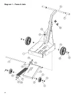
Page 20: ...20 Diagram 1 Frame Axle...

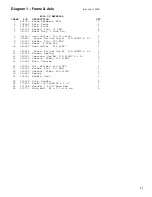
Page 21: ...SAE 4 9 139569 Wheel 8 Inch Dia 2 10 049923 Lock Collar 625 w SS 3 11 020551 Screw Set Soc Cup Pt 312 18UNC x 25 1 12 139638 Anchor Spring 1 13 020323 Capscrew Hex Hd 375 16UNC x 1 00 2 14 020199 Loc...

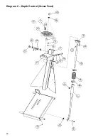
Page 22: ...22 Diagram 2 Depth Control Screw Feed...

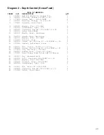
Page 23: ...sy Revolving 1 12 020766 Washer Flat 500 SAE 2 13 174956 Bracket Stop 1 14 020552 Screw Set Soc Cup Pt 312 18UNC x 50 1 15 174994 Spacer Adjustment Screw 1 16 160164 Pin Clevis 50 Dia x 1 13 Lg 1 17 0...

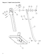
Page 24: ...24 Diagram 3 Depth Control Lock Bar...

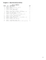
Page 25: ...vis 50 Dia x 1 13 Lg 1 7 020540 Screw Set Soc Cup Pt 250 20UNC x 25 1 8 177239 Pin Rue Ring 50 DIA 1 9 139626 Pointer Depth 1 10 020461 Screw Mach Ph Hd 10 24UNC x 875 1 11 020194 Locknut Fiber 10 24U...

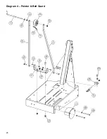
Page 26: ...26 Diagram 4 Pointer Belt Guard...

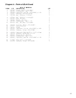
Page 27: ...220 Wheel 3in Dia 1 9 020786 Lockwasher Split 375 1 10 020136 Nut Std Hex 375 16UNC 1 11 020199 Locknut Fiber 375 16UNC 1 12 172137 Rope Pointer 1 13 162761 Clamp 2 14 020395 Capscrew Soc Hd 250 20UNC...

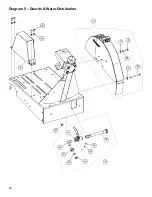
Page 28: ...28 Diagram 5 Guards Water Distribution...

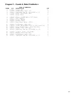
Page 29: ...90 Brass 1 7 040270 Hose Adapter 1 8 045640 Filter Washer 1 9 040254 Washer Hose 1 10 139616 Hose Assy Water MC18 1 11 020782 Lockwasher Split 10 2 12 196039 Screw Rd Hd Mach 10 24 x 500 Cross Z P 2 1...

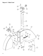
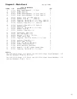
Page 30: ...30 Diagram 6 Blade Guard...

Page 31: ...61 Capscrew Hex Hd M5 x 0 8 x 20mm 4 9 173047 Washer Flat M5 2 10 172316 Locknut Fiber M5 x 0 8 2 11 020782 Lockwasher Split 10 2 12 172011 Nut Hex Hd M5 x 0 80 4 13 040330 Spring 375 OD x 054 Dia 1 1...

Page 32: ...32 Diagram 7 Engine Bladeshaft...

Page 33: ...gine 9HP Honda Modified 1 196008 Engine 9HP Robin Modified 1 17 174962 Spacer Bearing 9R 13R 13H 2 18 174736 Plate Adapter 13H Only 2 19 020743 Washer Flat 375 Dia 8 20 020786 Lockwasher Split 375 13H...

Page 34: ...34 Diagram 8 Electric Motor...

Page 35: ...Set of 2 1 4 058020 V Belt 3VX280 2 5 139306 Motor 5HP 230 60 Alt Wiring 1 000923 Motor 5HP 3450 208 230 460 60 1 6 139540 Adapter L H 1 7 139538 Adapter R H 1 8 020743 Washer Flat 375 Dia 8 9 048740...

Page 36: ...36 Diagram 9 Air Motor...

Page 37: ...4 13 020408 Screw Mach Rd Hd 10 24UNC x 0 75 4 14 020194 Locknut Fiber 10 24UNC 4 15 139537 Water Valve 1 2 NPT 1 16 020836 Elbow 45 Female 1 2 NPT 1 17 139641 Air Filter Regulator Unit 1 18 020762 Wa...

Page 38: ...375 16UNC x 2 00 2 5 020199 Locknut Fiber 375 16UNC 4 6 020322 Capscrew Hex Hd 375 16UNC x 75 2 7 139722 Hose 3 8 ID x 4 4 1 8 020049 Hose Clamp Worm Drive 2 9 174016 Fitting Hose Barb 3 8 ID x 3 4 M...

Page 39: ...39 NOTE NOTA...

Page 40: ...oad Kwun Tong Hong Kong Phone 852 2516 6602 FAX 852 2516 6605 E mail targethk netvigator com Target Japan Korea Taiwan 1803 36 Oyama Machi Machida Shi Tokyo 194 0212 Japan Phone 8142 797 0212 FAX 8142...

Reviews: