An Evaluation System for the TAOS Light-to-Frequency Converters
www.taosinc.com
9 of 10
Page 1: ...opriate drive letter in the above command to install the software CD ROMs are commonly D The installation program will guide you through the product installation Refer to the ReadMe file on CD for the latest installation instructions USB EVM HARDWARE AND DRIVER DESCRIPTION The specification and system requirements for the hardware portion of the Light to Frequency LTF EVM USB module follow System ...
Page 2: ...ith each daughterboard and these are labeled A and B on the motherboard Frequency measurements period measurements and PWM control of the daugherboard LEDs are performed by either the BASIC Stamp or the coprocessors under BASIC Stamp control The EVM is shipped with an application programmed into the BASIC Stamp which controls the communication between the BASIC Stamp the sensor coprocessors and th...
Page 3: ...connector on the bottom of the daughterboard with either of the sockets A or B Note that the connector is polarized and the daughterboard should be inserted such that the two mounting holes in the corners opposite the side with the connector align over the threaded standoffs on the motherboard Press firmly over the connector to make sure that the daughterboard is seated firmly in the socket As exp...
Page 4: ...ly a Strip Chart recorder window can be invoked which displays the data in a graphical representation Each window is explained in more detail in the following sections Figure 2 Light to Frequency EVM Main Window Control Window The control window appears at the far left of the main application window It provides control over measurement mode and measurement update rate of both daughterboard windows...
Page 5: ...ives a relatively high count value in a reasonable amount of time integration time For lower frequencies a longer integration time is required to get a high count value high resolution In this case Period measurement mode can be used which will result in a higher count value in a shorter amount of time since only the measurement of one period or cycle is required For very low frequencies less than...
Page 6: ...y cycle or percentage of time that the signal is high of the drive signal to the LED This drive signal is then low pass filtered to provide a continuous DC signal If the duty cycle is low then the percentage of time that the LED is on is low near 0 and the average power and thus the brightness is low If the duty cycle is high near 100 then the average power delivered to the LED is nearly maximum l...
Page 7: ...ed as the standard for subsequent measurements The ratiometric measurement is calculated as follows Reading Signal Reference Note that both measurement options can be used together In this case the following calculation is used Reading Signal Ambient Ambient Reference Ambient Ambient Strip Chart The Strip Chart window is invoked by selecting menu option View Strip Chart The Strip Chart is a graphi...
Page 8: ...An Evaluation System for the TAOS Light to Frequency Converters www taosinc com 8 of 10 Appendix ...
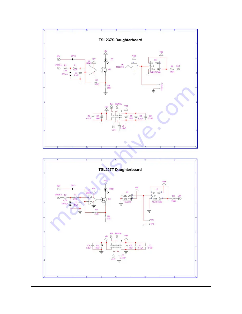
Page 9: ...An Evaluation System for the TAOS Light to Frequency Converters www taosinc com 9 of 10 ...
Page 10: ...An Evaluation System for the TAOS Light to Frequency Converters www taosinc com 10 of 10 ...