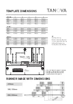
RUNNER POSITIONS are on each short end of the template provided, marked 1 RHF and 1 LHF
1. Hold Template against the underside of the cabinet top rail and 1 RHF flush with the right-hand cabinet side,
and mark runner fixing positions as shown on template.
2. Repeat on left hand side of cabinet using the 1 LHF edge of template.
3. Fix Runners to cabinet THROUGH TOP ROW OF HOLES IN RUNNERS using either 3 x M6 x 11 Euro Screws
(Pre-drill with 5mm) or 3 x 6g x 15mm wood screws (Pre-drill with 3mm) per tab minimum.
4. Position Top Cover against the top of the cabinet and 3mm back from the front, screw off with the 8g x 15mm
Pan screws. Note: Top Cover only supplied standard with waste systems.
5. Extend runners out the front of cabinet. Slide bin frame onto runners and engage tabs at rear, push bin assembly
on firmly until the front connection “Clicks” into place.
DESIGNER SERIES
INSTALLATION INSTRUCTIONS
USE IN CONJUNCTION WITH THE FULL SIZE TEMPLATE SUPPLIED WITH YOUR UNIT
STEP 1
STEP 2
DRAWER FRONT TEMPLATE is on the long edge of the template provided, marked 2 Centre Top.
6. On the back of the drawer front, mark the Center line of the drawer front. Measure down from the top of the
drawer front the desired amount of Cabinet overlay.
7. Align the template center marks with the marked drawer front center line.
8. Move template upwards until flush with overlay position, mark drawer lower bracket and gallery rail fixing
points and fit drawer and gallery rail connector brackets with the 6 x 6g x 15mm countersunk screws.
NOTE: If you have a LOWSIDE TDS80 system to suit 800 Cabinet, take notice of the offset LH and RH centerline
points,
“Centre TDS80LH” and “Centre TDS80RH”
9. Fit drawer front to drawer connector brackets.
Drawer Insertion
Drawer Front Assembly & Removal
Screw-on
Assembly
‘Click’
Removal


