OPERATING MANUAL
PLASMA CUTTING
GB
Inglese
GB
4.2 Cutting start-up
Read the standards CEI 26/9 – CENELEC HD 407 and CEI 26.11 – CENELEC HD
433 carefully before using the equipment, and make sure the cable insulation is
fully intact. Make sure the trigger has not been pressed.
Turn the machine on using the switch B. The warning lamp D will light and thermal
lamp E will blink for 5 sec. to indicate that the machine is on.
Press the torch trigger briefly to open the flow of compressed air ; for first start the
-
re isn’t pilot arc but only air flow to clean the air hose from . Since the arc is
not lit, air leaves the torch for 20-25 sec.
Connect the grounding clamp to the workpiece. The cutting circuit must not be
deliberately placed in direct or indirect contact with the protective wire except in the
workpiece. If the workpiece is deliberately grounded using the protective conductor,
the connection must be as direct as possible and use a wire of at least the same
size as the cutting current return wire, and connected to the workpiece at the same
point as the return wire clamp or a second grounding clamp placed in the immedia-
te vicinity. Every precaution must be taken
to
avoid stray currents. Use the knob C to
select the cutting current.
Make sure that the grounding clamp and workpiece have a good electrical contact,
especially with painted, oxidized or insulated sheet metal.
Do not connect the grounding clamp to the part of the material that is to be remo-
ved. Press the torch trigger to strike the pilot arc.
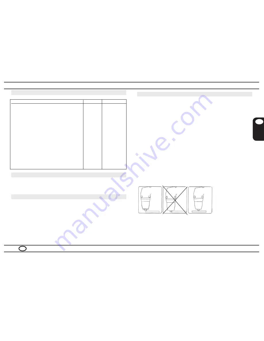
Begin cutting as shown in fig. 5a, avoid starting as shown in fig. 5b. Further during
cutting operation the torch have to keep in contact with workpiece in order to avoid
torch overheating
(Picture 5c).
Picture 5a Picture 5b Picture 5c
3.4 Technical specifications table (table 2)
Technical data
Site Cut 10
Main supply (-15%/+15%)
VAC
1ph x 230V
Frequency
Hz
50/60
Main power (60%)
KVA
2,6
Open
circut
voltage V0
V
250
Current range I2
A
13-25
Arc pilo
t
current I2
A
11-13
Cutting current I2 (X%)
A
25
I2 (60%)
A
25
I2 (100%)
A
20
Recommended cutting capacity
mm
6
Maximum cutting capacity
mm
8
Severence cutting capacity
mm
10
Gas flow
bar
Air compressor.
Insulation class
F
Protection degree
IP
21S
Dimensions
mm
425x210x415
Weight
Kg
19,0
4. Start-up and use
The machine must be installed by qualified personnel. All connections must be
made in compliance with current safety standards and full observance of safety
regulations.
4.1 Main supply connection
Connect the power cord A: the yellow-green cable wire must be connected to an
efficient grounding socket on the system. The remaining wires must be connected
to the power supply line by means of a switch placed as close as possible to the
cutting area, to allow it to be shut off quickly in case of emergency.
The capacity of the cut-out switch or fuses installed in series with the switch must
be equal to the current I1 absorbed by the machine.
The absorbed current I1 may be determined by reading the technical specifications
shown on the machine under the available supply voltage U1 .
Any extension cords must be sized appropriately for the absorbed current I1.
PAGE 5
pump


