

Operations Table
Compatible Base Units / Repeaters
Battery Charger for RTR-601
(with USB communication)
Network Base Station
RTR500BW (Wired/Wireless LAN Type)
RTR-500NW (Wired LAN Type)
RTR-500AW (Wireless LAN Type)
Wireless Base Station / Repeater
RTR500BC / RTR-500
Battery Charge Dock
RTR-600BD
Accessories Included in
Package:
• AC Adaptor AD-05A3
• USB Cable US-15C
• Wall Mount Screws x 3
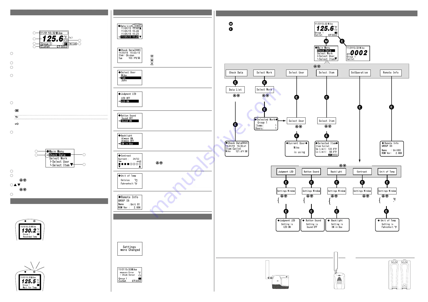
Menu Contents
[Check Data] > [Data List] > [Check Data]
By selecting the [Check Data] menu, all recorded
data in the Remote Unit is displayed in a list in
descending order (from newest to oldest data).
Select data by moving the cursor and press the
<ENT> button to view detailed information.
The left screen shows the 83rd data reading highlighted by
the cursor.
Details of the selected data (date and time of
recorded data, measured-item, user name, and
judgement result) will be displayed.
Judgement OK
Lower Limit Error
Upper Limit Error
[Select User] / [Select Item]
Select from the list of Users and Items setup in
the software.
If you have registered Work Groups, it is also
possible to select from the [Select Work] menu.
[Judgement LED]
By setting to "LED ON", the Judgement LED will
blink when a measurement exceeds the set up-
per or lower limit*.
* Upper and lower limits can be set using the
software.
[Button Sound]
Turn ON or OFF the beep which sounds when a
button is pressed.
[Backlight]
The "ON in Use" option will backlight the display
for three seconds only during operation.
[Contrast]
Use
to adjust the contrast of the display.
[Unit of Temp]
Select Celsius [°C] or Fahrenheit [°F].
[Remote Info]
The Group ID* and Remote Unit Name can be
viewed here for the unit being used.
* The Group ID is automatically assigned upon
registering a Remote Unit.
Message Display
Settings Change Message
If any settings changes have been made via wireless communi-
cation to the unit in use, a notification message will be displayed
for about two seconds. After that, you will be automatically
returned to the top screen.
This message will be displayed regardless of
what settings have been made in the unit.
Even when the power is off, the unit will auto
-
matically turn on to display the message.
Sensor Error Message
Please contact your local distributor if you see
this message.
How to Read the LCD Display
Top Screen
By turning the power to ON, the Top Screen, such as below, will
appear.
1
2
3
4
5
6
1
Current Date/Time and User Name
A maximum of 8 characters can be displayed for a user name.
2
Current Temperature (°F/°C)
3
Work Group Name
A maximum of 8 characters can be displayed as a work group name.
4
Measured Item and Count No.
The item being measured and a count number to show how many times
this item has been measured are shown here. A maximum of 12 charac-
ters can be displayed for a measured item. The count number will be reset
to zero every time a Work Group Table is sent via software.
The above screen shows the temperature of a cutlet that has been mea-
sured two times.
5
Icons (Battery Level / Communication Antenna / Button Lock)
This icon shows the remaining amount of battery power. When
the battery is too low to measure temperature, the "Please
charge batteries" message will appear.
This icon appears during wireless communication with the Base Unit.
This icon appears when "Button Lock" is set to ON in the software.
Button operation will be OFF for all buttons except for the <REC> and
Power buttons.
6
Recording Mode (Endless)
Main Menu Screen
By pressing the <MENU> button, the Main Menu will appear as
shown below.
1
2
3
4
1
Menu Title
2
Cursor
Use to move the arrow cursor up and down.
3
Use to scroll the screen up and down.
4
Currently Selected Item (Highlighted)
Details about the LED Light (when REC is pressed)
Orange LED: ON (Normally)
Normally the orange LED turns on, and the recorded tempera-
ture is displayed.
After about three seconds, the orange
LED turns off and the display automati
-
cally returns to the top screen.
Orange LED: Blinking ("Wait for Temp")
When the "Wait for Constant Temp Settings" has been set to ON
in the software and temperature is not stable, the orange LED
blinks meaning a recording is pending*.
Do not remove the sensor from an object
being measured while “Wait for Temp” is
on display and the orange LED is blinking.
* If the temperature is not stabilized even
after 15 seconds have elapsed, recording
will not be performed and you will be
returned to the top screen.
= Press the <MENU> button.
= Press the <ENT> button.
(To get back to the previous screen, press the <MENU> button.)
<Main Menu : Press
to select a Menu.>
<Set Operation Menu : Press
to select a Menu.>
Top
Screen
Main
Menu
Screen
Enlarged view of the count
number for the item being
measured
Press to
select data.
Press to
select group.
Press to
select a user.
Press to
select an item.
Press
to select:
LED OFF
LED ON
Press
to select: Press
to select:
Press
Press
to select:
Sound OFF
Sound ON
Always ON
Always OFF
ON in Use
to adjust the
contrast level
Celsius
Fahrenheit
F


