background image

English - 10

9 - English

LCD  MONITOR

User s Manual

9

LCD  MONITOR

User s Manual

10

Remote signal wirdow

This window is for the receiving signal from remote controller

Do not hide this window.

Power Indicating LED

Green : Normal mode
RED : Standby mode

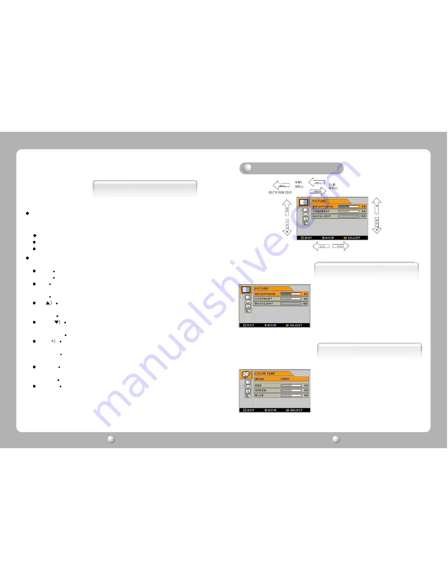
On-Screen Display (OSD) Function Button

MENU : With OSD deactivated, Activated to OSD menu

With OSD activated, Exit from main menu or sub menu.

OK  :  With OSD deactivated, you can see the kind of displayed source on the right 

bottom side of the screen.

With OSD activated, Enter sub menu and change each sub menu item

UP(

: With OSD deactivated, Hot key of the brightness control and increases 

the brightness.
With OSD activated, move the cursor upward.

DOWN(

: With OSD deactivated, Hot key of the brightness control and 

decreases  the brightness.
With OSD activated, move the cursor downward.

PLUS(

:

With OSD deactivated, Hot key of the contrast control and increases
the contrast.

With OSD activated, enter sub menu and increases the adjustment of 

the selected function.

MINUS(-) :  With OSD deactivated, Hot key of the contrast control and decreases 

the contrast.

With OSD activated, decreases the adjustment of the selected function.

SOURCE :

For the extra function, normally no need to use this button.

Functions

COLOR TEMP

1. MODE

Change the Color mode ( 6500, 7200, 9300, USER )

2. RED

Red balance (Only Working with USER mode)  (Range : 0~100)

3. GREEN

Green balance (Only Working with USER mode)  (Range : 0~100)

4. BLUE

Blue balance (Only Working with USER mode)  (Range : 0~100)

Adjusting  OSD 

PICTURE

1. BRIGHTNESS

Increase or decrease the brightness (Range : 0~100)

2. CONTRAST

Increase or decrease the Contrast (Range : 0~100)

3. BACK LIGHT

Increase or decrease the CCFL back light luminance (Range : 0~100)

Summary of Contents for FS-L4201C

Page 1: ...Printed in Korea Part No 942667020001 01 TFT LCD Color Monitor FS L4201C User Manual English www tandberg net...

Page 2: ...s may cause harmful interference to radio commu nications However there is no guarantee that interference will not occur in a particular installation if this equipment does cause harmful interference...

Page 3: ...DVI Connector for Digital TMDS 15 Pin D Sub connector for Analog RGB User s Manual 42 LCD Monitor Parts Connection to Signal Source LCD MONITOR User s Manual 3 LCD MONITOR User s Manual 4 This monitor...

Page 4: ...e 3 Power on the monitor and computer 4 Connection is finished D Sub Analog Data in DVI Digital Power source connection Signal cable connection Coaxial S PDIF Input Audio amp Output Out Drawing of pro...

Page 5: ...n Rear side Remote signal window Power indicating LED Power Management Feature Power management system of this monitor can not be corresponded with VESA DPMS when the display video signal is none beca...

Page 6: ...l and decreases the brightness With OSD activated move the cursor downward PLUS With OSD deactivated Hot key of the contrast control and increases the contrast With OSD activated enter sub menu and in...

Page 7: ...74 25 108 87 75 Resolution Horizontal Frequency KHz Vertical Frequency Hz Clock Frequency MHz PC Supported Mode SETUP 1 IMAGE SIZE Change the image size Scaling mode Full Fill aspect 1 1 2 SHARPNESS...

Page 8: ...6 Ground Red 15 DDC Clock 7 Ground Green 8 Ground Blue 1 8 17 24 9 16 24 Pin DVI D 2 1 RCA Pin No Assignment Pin No Assignment 1 T M D S Data2 13 No Connect 2 T M D S Data2 14 No Connect 3 T M D S Da...

Page 9: ...others and switch on Troubleshooting Type a si TFT Active matrix Screen Size 106 7cm Diagonal Maximum Resolution 1366 X 768 60 Hz Pixel Range 0 681 H mm X 0 227 V mm Display Colors 16 7M RGB 8 bit da...

Page 10: ...t the plug in case of thunder and lightening To prevent fire and electric shock do not try to take the monitor apart or repair it yourself Contact your local service station or customer service center...

Page 11: ...19 English...

Reviews: