background image

D13728.09 Page 1

Installation

3000/6000

Profile

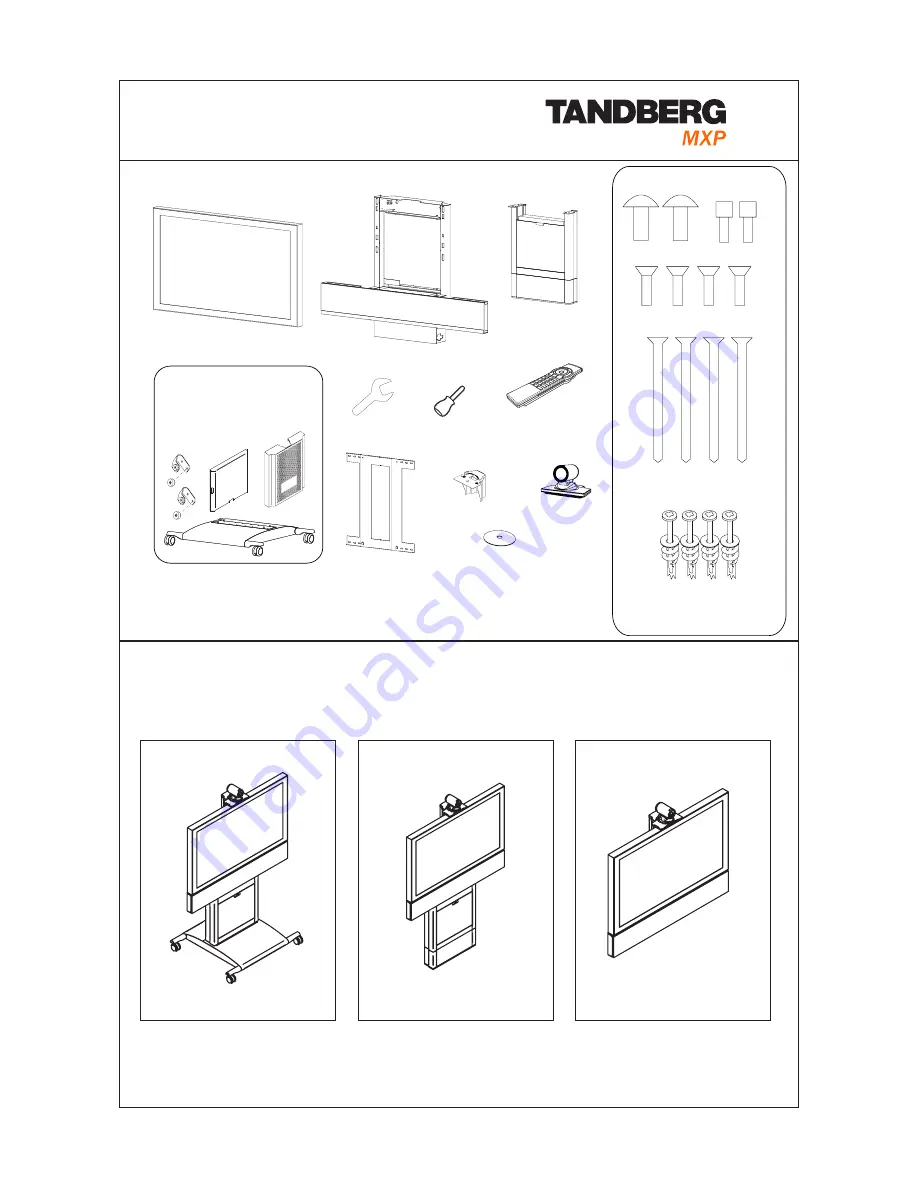
For mounting of the Wheel base, Foot mount or Wall mount, follow the respective instructions on page 2-6.

2 Mounting

Wheel base

Foot mount

Wall mount

1 Unpacking

Monitor

Bolts:

Wall Bracket

Camera

Top Module

Cable Cover, Back 

Cover and Base

(Wheel base option)

Camera Stand

Column

and Foot

2x Type A

2x Type B

4x Type C

        4x Type D

+ 4x plugs for concrete

Wrench

Remote

Control

Screw driver

(for removing the handles

on 6000 MXP Profile 50”)

User Manual on CD

        4x Type E

+ 4x washers for 

gypsum/plasterboard

For mounting of the Wheel base, Foot mount or the Wall mount version,

follow the respective instructions on the following pages.

Summary of Contents for 3000 MXP Profile

Page 1: ...et Camera Top Module Cable Cover Back Cover and Base Wheel base option Camera Stand Column and Foot 2x Type A 2x Type B 4x Type C 4x Type D 4x plugs for concrete Wrench Remote Control Screw driver for removing the handles on 6000 MXP Profile 50 User Manual on CD 4x Type E 4x washers for gypsum plasterboard For mounting of the Wheel base Foot mount or the Wall mount version follow the respective in...

Page 2: ...ng the Monitor Also connect speaker and amplifier cables Put excess cable length back behind monitor 5a Mount the Monitor 43 50 for 32 see 5b On all products except TANDBERG 3000 MXP 32 Profile Use 2x type A bolts to fixate the Monitor Caution Be careful not to squeeze fingers or cables Rearrange cables if necessary Keep the Column in the package upside down while disassembling the Foot WARNING Do...

Page 3: ...age 3 Wheel base Mount the Magnet Brackets behind the Column and attach the Cable Cover to the magnets You may have to rearrange the cables Mount the Back Cover on the back side of the Top Module 6 Mount the Cable Cover and the Back Cover 8 Connecting external devices If external deivces are connected to the system lead the cables through the hole in the cable cover 3000 6000 Profile There are acc...

Page 4: ...lts in front and on sides from underneath Remove rubber band before mounting Remove protection foil from acrylic plate Step 2 Tighten nuts in position a and b after mounting 3 Connect cables and mount the Monitor Pull cable through Camera Stand and place it behind the Monitor Ensure that the Camera Stand is properly connected to the magnets on top and behind Plug cables to Camera and place camera ...

Page 5: ...e sure to select holes that align with the wall studs pillars 1 B Mount the Wall Bracket to the wall Brick Concrete wall Make sure that the hooks on the Wall Bracket point upwards Mount the Wall Bracket horisontally in desired hight from floor recommended 762 mm 30 Use 4 type D bolts with concrete plugs 1 Drill a small initial hole 2 Drill a larger hole for plugs 3 Mount into specified holes with ...

Page 6: ...ration and press Save 1 Open the Control Panel Choose Control Panel from the main menu and press OK 3 System Configuration 3a LAN Configuration Open Network LAN Settings Make IP H 323 configuration and press Save Please read the user manual for further details TIP If the menu is not already present press the OK Menu key on the remote control to open the menu Navigate the menu with arrow keys and O...

Reviews: