background image

TANDBERG Videoconferencing System

17

Installation

System configuration

• Switch the system on by activating the power switch on the codec (located on the right hand side at the rear of

the codec). A green light is shown (located in the center on the front of the codec).

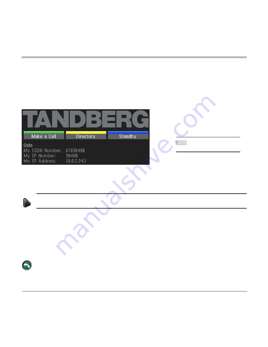
• After the system has performed a self-test routine, product logo and a ‘Welcome’ menu will be displayed on the

monitor.

connect

menu

• Enabled but unused ISDN lines (lines not active) should be disabled. Select the Quick Key ‘

System Info

’ (on

the remote control) to view line status.

P

RESS


M

ENU


ON


THE


REMOTE


CONTROL

. S

ELECT


THE


MENU

 ‘

T

ERMINAL

 S

ETTINGS

’, 

N

ETWORK

’, 

ISDN-BRI 

SETTINGS

’. S

ELECT


THE


RELEVANT

L

INE

 S

ETUP

’ 

MENU


AND


SET

 ‘

E

NABLED

: O

FF

’.

• Enter System Name to identify the system during an MCU conference. Select ‘

Utilities

’, ‘

System Name

’ and

enter the name using the number keys (as on a mobile phone).

• Select the language you want to use in ‘

Terminal Settings

’, ‘

Language

’.

• If you are using two monitors, set  ‘

Utilities

’, ‘

Dual Monitor: On

’.

• To activate MultiSite and/or Presenter, enter an option key (see paperwork accompanying your system), see

Terminal Settings

’, ‘

Software Options

’.

• Press 

C

ONNECT

 on the remote control.  A dial tone should be heard if the network is active.

• Using the monitor remote control, adjust the volume on the monitor to a level of your choice. This
volume will be the default volume for all calls.

T

HESE


SETTINGS


ARE


ESSENTIAL

FOR


OPTIMAL


SYSTEM


SET

-

UP

.

NOTE

Summary of Contents for 2500

Page 1: ...1 Software version E3 B8 D12155 10 This document is not to be reproduced in whole or in part without permission in writing from UserManual ...

Page 2: ...2 TANDBERG Videoconferencing System ...

Page 3: ...m or by any means electronically mechanically by photocopying or otherwise without the prior written permission of TANDBERG Nationally and internationally recognized trademarks and tradenames are the property of their respective holders and are hereby acknowledged Portions of this software are 1996 2004 RADVision Ltd All intellectual property rights in such portions of the Software and documentati...

Page 4: ... produce heat Grounding or Polarization Do not defeat the safety purpose of the polarized or grounding type plug A polarized plug has two blades with one wider than the other A grounding type plug has two blades and a third grounding prong The wide blade or third prong is provided for your safety If the provided plug does not fit into your outlet consult an electrician Power Cord Protection Route ...

Page 5: ...20 Welcome menu 20 Basics 21 Making and ending calls 22 Directory 27 Microphone on off 30 General use 30 Adjusting volume 30 View outgoing video selfview 30 Do Not Disturb Sleep Mode 31 Selecting video sources 32 Controlling the Main Camera 32 Voice Activated Camera Positioning 33 Presets 34 Far end camera control FECC 35 Sending and receiving snapshots 36 Duo Video 37 MultiSite MCU 39 PC Presente...

Page 6: ...work Configuration 69 LAN Settings 76 Call Settings 84 Dataport configuration 87 Language 89 Software Options 89 Diagnostics 90 Peripheral Equipment 94 Interfaces 94 Dual Monitor 96 Document camera 97 Multiple controllable cameras 98 AudioScience microphone 99 Tracker 99 Video Cassette Recorder VCR 100 TelephoneAdd On 101 Extra fixed cameras 101 PC applications 102 PC SoftPresenter 102 Additional ...

Page 7: ...icipants at the far end to simultaneously watch a presenter on one screen and a live presentation on the adjoining screen Digital ClarityTF participants enjoy presentations of exceptionally high quality resolution video PC PresenterTF an easily accessible PC connection plug supporting XGA resolution PC SoftPresenterTF show PC images via your LAN connection supporting XGA resolution Natural VideoTF...

Page 8: ...twork Settings Inputs Outputs AGC Settings Restore Audio Defaults Level Settings Level Settings Line 3 Setup Exit Diagnostics Focus Brightness Whitebalance Video Name VGA Settings Disconnect Site Terminate Meeting Request Floor Release Floor Chair Control Terminal Names Floor to Site Quick Menu View Site End View Release Chair Take Chair Rel Floor to site System Info Call Status View Current Setti...

Page 9: ...TANDBERG Videoconferencing System 9 The TANDBERG 2500 Videoconferencing System At a glance the TANDBERG 2500 system ...

Page 10: ...ositions using the remote control Monitor s The monitor displays the far end and near end videoconferencing sites in addition to the menus video from connected video sources and high resolution images You can also connect a second monitor for displaying self view still images and Duo Video Codec The Codec is the heart of the system The main task for the Codec is the compression of outgoing video a...

Page 11: ...menu connect directory disconnect Cabinet The cabinet is easily movable with large wheels and handles The Codec is located inside the cabinet Below the Monitor s there is room for additional equipment e g a VCR Remote control The remote control is used to control all functions of the system If the screen saver is activated black monitor touching the remote control will automatically wake up the sy...

Page 12: ...e The ideal location for the microphone is on a flat surface at least 2m 6 5 ft from the front of the system The microphone cable should always point towards the system You can connect up to three microphones The system will automatically equalize sound levels Loud and soft voices are picked up and transmitted to the far end at approximately the same level ...

Page 13: ...cations network This network type is only to be used behind a PABX X 21 network type is not approved for connection directly to the telecommunications network This network type is only to be used together with already approved equipment and is not meant for direct connections to the telecommunication networks V 35 RS 449 RS 366 network type is not approved for connection directly to the telecommun...

Page 14: ...monitor on top of the cabinet top plate and ensure it is stable You may fasten the monitor to the cabinet using the securing kit Take the camera and remove the plastic backing from the double sided tape pads on the base of the unit Place the camera centrally on top of the monitor close to the front If the system has two monitors place the camera on the left monitor where menus and incoming picture...

Page 15: ...ution socket 2 Monitor cables Connect the S video cable to the input on your monitor see drawing For Scart monitors use the Scart adapter 3 Microphone cable Connect the microphone cable to the microphone 4 Camera cable Connect the camera cable from the S Video output on the camera to the S Video input Main Cam on the codec Connect also the control cable between the RJ 45 on the camera and the Data...

Page 16: ...D YOUR ISDN LINE SEE APPENDIX 1 5b Other networks using the External Network interface If you are using other networks please refer to External Network Settings and Appendix 2 6 LAN cable To use the system on LAN connect a LAN cable from the Ethernet connector on the system to your LAN TANDBERG LOEWE 33 29 PAL monitor For the TANDBERG LOEWE monitor external input 1 199 AV1 is automatically selecte...

Page 17: ...GS NETWORK ISDN BRI SETTINGS SELECT THE RELEVANT LINE SETUP MENU AND SET ENABLED OFF Enter System Name to identify the system during an MCU conference Select Utilities System Name and enter the name using the number keys as on a mobile phone Select the language you want to use in Terminal Settings Language If you are using two monitors set Utilities Dual Monitor On To activate MultiSite and or Pre...

Page 18: ...ed to be configured Press MENU on the remote control Select the menu Terminal Settings then Network Set Current Network to the network you want to use Specify the settings for the selected network in one of the menus For details follow the instructions in chapter Terminal Settings Network Configuration in this manual For further information refer to the examples in Appendix 1 Connecting the system...

Page 19: ...rol Select the menu Terminal Settings then LAN Settings Specify the necessary LAN settings according to the instructions from your LAN administrator If there is an H 323 Gatekeeper present on your LAN see also H 323 Settings For details follow the instructions in chapter LAN Settings in this manual ...

Page 20: ...below After a few seconds you should see the Welcome menu on the monitor If this does not help verify that your monitor is switched on To switch the monitor on you normally push the power button on the front of the monitor depending on monitor type Welcome menu After the system has performed a self test routine product logo and a Welcome menu will be displayed on the monitor This menu should provi...

Page 21: ...screen The text inside the blocks will change depending on which menu is selected The three Quick Keys have different colors Preset keys Activate pre stored camera positions Video source keys Activate connected video sources Camera control and menu navigation keys Frequently used keys allowing you to control your own camera and the far end camera control your volume select and move self view switc...

Page 22: ...f channels are dropped during a meeting Downspeeding automatically maintains the connection without interrupting the call in progress The SoftMux also enables you to dial to other videoconferencing equipment phones and mobile phones in the same way and provides you with on screen real time feedback on the progress of a call LAN call To make a call via a LAN enter an IP address by using a as the do...

Page 23: ...star after the number and then enter the sub address extension address Example 12345678 10 number Sub address extension address MCU password When calling to external MCU s requiring a password TSC 1 this password can be added after the star If no password is specified a menu will prompt you to enter the password after connected to the MCU SUB ADDRESS IS USED TO ADDRESS DIFFERENT SYSTEMS ON THE SAM...

Page 24: ...ll then be displayed NOTE TIP Choose the preferred quality by selecting the desired call rate in the Call Rate field You may also press the Set as Default Quick Key in order to make the selected bandwidth the default bandwidth for subsequent calls Set Set Restrict 56k to On to make a restricted call An indicator 56k will be shown behind the number RESTRICTED CALL ARESTRICTED CALL IS A CALL TO A 56...

Page 25: ... all subsequent calls If Auto is selected the system will select a network based upon the following criteria If an IP address e g 123 3 0 12 is entered LAN H 323 is selected If the first digits in the number match those set in H 323 Prefix under H 323 Settings LAN is selected In other cases ISDN H 320 is selected If you want to assign a specific prefix to the network selection or if you want to de...

Page 26: ...answer facility is switched off See Utilities in Advanced use End a call To end a call press DISCONNECT Correcting keying mistakes To delete the last digit or character entered press DELETE ENDING A CALL SWITCHING OFF THE MONITOR S WILL NOT DISCONNECT A CALL TO DISCONNECT A CALL YOU SHOULD PRESS THE DISCONNECT KEY connect disconnect delete TIP ...

Page 27: ...e entries will not be displayed when you are in a call By using the dataport file system or external management systems like the TANDBERG Management Suite it is possible to store 400 additional entries These entries can only be changed from the dataport or the management system When the system receives an incoming call and the calling party s number is found in the directory the calling party s na...

Page 28: ...d 2x64 or 2x56 calls 3 Select Quality to specify call rate to be used 4 Select Set Restrict 56k to On to restrict the call rate A restricted call is a call to a 56Kbps network 5 Select Net to specify the network profile to be used See Selecting setting default network 6 Select Save to save the entry and return to the Directory menu Delete Entry When Delete Entry is pressed the selected entry is de...

Page 29: ... 512KBPS TWO ENTRIES ARE ADDED ONE WITH 384KBPS AND ONE WITH 128KBPS 1 SINCE ALL SITES MUST USE THE SAME BANDWIDTH QUALITY PER SITE WILL BE 128KBPS 2 IN ADDITION MAXIMUM BANDWIDTH PER SITE CANNOT EXCEED THE TOTAL BANDWIDTH AVAILABLE DIVIDED BY THE NUMBER OF SITES IN THIS CASE THE MAXIMUM BANDWIDTH PER SITE CANNOT EXCEED 512 2 256KBPS IF THE BANDWIDTH IN 1 IS HIGHER THAN THIS BANDWIDTH THE QUALITY ...

Page 30: ... 3 AND AUDIO4 IT WILL NOT MUTE AUDIO FROM THE AUX AND VCR INPUTS NOTE move pip General use Adjusting volume Press the VOLUME keys to adjust the volume level An on screen indicator will show the current level View outgoing video selfview Press the SELFVIEW key to view your outgoing video To change the image being viewed on the monitor during a call press SELFVIEW until the desired image is shown fa...

Page 31: ...hown On Screen Symbols The system has a number of symbols signalling different settings This symbol will be shown when the volume is turned off on the system This double padlock symbol will be shown when AES encryption Secure Conference is active This padlock symbol will be shown when DES encryption Secure Conference is active This open padlock symbol is shown during the initialization phase for e...

Page 32: ... Settings in Advanced use When Sleep Mode is selected the following quick keys are displayed Pressing Sleep Now puts the monitors in sleep mode The system will still accept incoming calls Pressing 60 Minutes or 3 Hours will delay entering sleep mode accordingly Pressing any key or picking up the remote control will deactivate Do Not Disturb Sleep Mode Selecting video sources Press to select the vi...

Page 33: ...g by pressing CamTrack On in the Preset 0 9 menu which is activated by pressing the P button on the remote control An on screen indicator CamTrackOn will appear When activating another video source e g document camera camera tracking will be temporarily disabled until you re select MainCam or a MainCam preset Pressing MIC OFF will temporarily disable camera tracking A Voice Detector makes the syst...

Page 34: ...P3 are the same presets as when pressing P and then a number key 1 3 Storing presets To store the current camera position audio and video source Press STORE once and wait for the on screen indicator to appear Then press one of the keys P1 P2 P3 or a number key 0 9 store P1 P2 P3 Storing preset 10 to 15 To store preset 10 15 the TANDBERG Tracker has to be used Select which preset to be used on the ...

Page 35: ...o control the far end camera use the keys below for pan tilt and for zooming Far end presets can be activated by pressing the keys P1 P2 P3 or the number keys 0 9 to activate presets P0 P9 Selection of far end videosources is achieved by pressing the buttons below when in FarEndCamera mode To prevent others controlling your camera select Far End Camera Control Off in Utilities zoom doc cam main ca...

Page 36: ...ed on your screen Press SELFVIEW to return to normal view REQUIRES AUTO DISPLAY SNAPSHOT ON IN PRESENTATIONS Receiving a snapshot A received snapshot will automatically be displayed on your screen Press SELFVIEW to return to normal view REQUIRES AUTO DISPLAY SNAPSHOT ON IN PRESENTATIONS Requesting a snapshot Press FAR END until the FarEndCamera on screen indicator is displayed Press SNAPSHOT A sna...

Page 37: ...owing menu will be displayed Select video source to transmit on Duo Video Press CONNECT to add Duo Video AUTOMATIC DUO VIDEO HANDLES DUO VIDEO WITHIN THE SAME CALL IT IS NOT NECESSARY TO MAKE A NEW CALL AND THE CONNECT TIME DECREASES A LOT DUO VIDEO BORROWS BANDWIDTH FROM THE MAIN CONNECTION WHEN DUO VIDEO IS CLOSED THE BANDWIDTH IS RETURNED TO THE MAIN CONNECTION THIS DUO VIDEO IS ALSO UNI DIRECT...

Page 38: ... source in PIP and vice versa Pressing SELFVIEW will not change anything on the main monitor in a dual monitor setup Pressing MOVE PIP will move PIP only on the 2nd monitor in a dual monitor setup Controlling the camera changing video source and using presets will affect the video source currently displayed in full screen mode EXAMPLE IF DUO VIDEO IS SHOWN IN FULL SCREEN ON THE 2ND MONITOR PRESSIN...

Page 39: ...lished with the first site the other sites are connected one by one It is possible to either dial out to the sites or the sites can dial in to the MultiSite Optional feature SEE UTILITIES CONTINUOUS PRESENCE TO CHANGE MODE TIP Both ISDN IP and mixed ISDN IP conferences can be encrypted if all systems supports encryption For encrypted calls there is also a maximum bandwidth of 768 Kbps for the whol...

Page 40: ...ntinuous Presence mode The cascaded systems connect to two other video sites plus one audio site each These systems will automatically run Voice Switched mode and transmit a full screen image to the host Establishing MultiSite meetings using Directory It is possible to pre define meetings using the Directory All sites will then be connected automatically instead of having to add sites one by one P...

Page 41: ... that you do not run out of bandwidth EXAMPLE IF THE SYSTEM HAS 512KBPS AVAILABLE AND YOU WANT TO CONNECT 3 SITES IN ADDITION TO THE HOST 128KBPS SHOULD BE SELECTED FOR THE FIRST CALL THE SYSTEM WILL THEN AUTOMATICALLY USE 128KBPS WHEN CONNECTING THE OTHER SITES When the first site is connected add a site to the conference using the following procedure IT IS POSSIBLE TO CONNECT SEVERAL TELEPHONES ...

Page 42: ...umber 3 To dial in to the MultiSite on ISDN PRI Dial the main number of the system My ISDN Number All sites can dial the same number To dial in to the MultiSite on IP Dial the IP Number or the IP Address of the system My IP Number My IP Address When the MultiSite receives an incoming call the following menu is displayed Pressing CONNECT is equivalent to pressing Accept Pressing DISCONNECT is equiv...

Page 43: ...PC transmits a supported VGA format see tip below Consult your PC operating manual to see how to transmit a VGA image from your PC typically Fn F5 PC Presenter input VGAIn VGAOutput PC SoftPresenter PC SoftPresenter is used to display PC images on your system without using a VGA cable The TANDBERG video conferencing system and your PC must be connected to a LAN In addition VNC Virtual Network Comp...

Page 44: ...e LAN Settings in Advanced use for further information Start your Web browser In the address field type the IP address of the codec Enter the password and the Web page of the codec will be shown The default password is TANDBERG THE SYSTEM MUST BE RESTARTED BEFORE CHANGES IN THE LAN SETTINGS MENU CAN TAKE EFFECT NOTE Text Chat Closed Captioning While in an ISDN or IP call to another system supporti...

Page 45: ...al Procomm Plus and so forth The system has been specially designed to work with interactive programs and includes a data channel that can send and receive data to and from the far end at speeds of up to 38 400 baud Streaming To view streaming select Streaming from the Web page of the codec See separate Streaming section in this manual for further information Not available together with XGA monito...

Page 46: ...t is possible to password protect the menus on the TANDBERG system To activate this feature specify a Menu Password in the Utilities menu By doing this only dialing and camera control commands will be available When pressing the MENU key the user will be asked to enter the Menu Password as can be seen below menu Advanceduse A MENU STRUCTURE MAP IS PROVIDED IN THE SECTION MENU STRUCTURE AT THE FRON...

Page 47: ... will not be transmitted This is useful if far end cannot handle these H 264 Auto Optimized video quality depending on what is available Off H 264 video compression and decompression will not be used capabilities VGA Resolutions Auto VGA capabilities VGA SVGA XGA and SIF capabilities will be transmitted and enabled Off VGA capabilities will not be transmitted Useful if far end can not handle these...

Page 48: ...sion and decompression H 263 Normal video compression and decompression H 261 Legacy video compression and decompression Off No video is transmitted Resolution Auto The setting of Video Auto Motion Sharpness in Call Quality will be used see tip above 4CIF Digital Clarity 704 x 576 pixels only for H263 CIF High resolution video 352 x 288 pixels QCIF Low resolution video 176 x 144 pixels H 331 Off S...

Page 49: ... far end will not see the snapshot while you are adjusting it Duo Video Quality Auto Optimized video depending on selected video source and bandwidth in use Motion Duo Video is optimized for smooth motion video This mode is ideal if the image from two W A V E cameras should be simultanously transmitted to the far end Sharpness Duo Video is optimized for sharp video Digital Clarity This mode is ide...

Page 50: ...deo Snapshot Source Select which video source Duo Video transmits If you want the document camera to be the default source when using Duo Video snapshot select Duo Video Snapshot Source DocCam To use the same video source as on the first connection for Duo Video snapshot select Duo Video Snapshot Source Current Auto Display Snapshot Select On to automatically display a received snapshot If this se...

Page 51: ...Off You must manually answer all incoming calls by pressing the CONNECT key Far end camera control On The far end will be able to Control your camera Select your video sources Activate your presets Request snapshots Off None of the four features above on the local system can be accessed by the far end however you will still be able to control the camera on the far end Dual Monitor On Selfview snap...

Page 52: ... video image of a different participant Off The active site will be displayed in full screen during a MultiSite conference Also called Voice Switched mode MCU status line On The MultiSite MCU DuoVideo indicators will be displayed and provide information about the conference Off The MultiSite MCU DuoVideo indicators will not be displayed Auto The MultiSite MCU DuoVideo indicators will be displayed ...

Page 53: ...e control the user will be asked to enter the Password written here Web Snapshots The system is able to generate JPEG snapshots and provide them to the world outside by request as http get or via ftp See Appendix 5 for descriptions of the possible snapshot files On Snapshots generation is enabled Off Snapshots generation is disabled SNAPSHOTS ARE NOT GENERATED IF THE CONFERENCE IS SECURE NOTE ...

Page 54: ... at the same time Chairman Control functionality enables one participant to control the meeting by selecting which of the conference participants is to be broadcasted to the other participants THIS SYSTEM HAS AS AN OPTIONAL BUILT IN MCU MULTISITE WHICH SUPPORTS UP TO 3 VIDEO CALLS 4 SITES AND ONE TELEPHONE CALL THE MULTISITE SUPPORTS BOTH VOICE SWITCHED AND CONTINUOUS PRESENCE MODE SEE SECTION MUL...

Page 55: ...r will change to Release Floor If View Site is selected View Site will change to End View Selecting Take Chair will send a request to take chair If granted the Quick keys will be If Floor to Site is selected Floor to Site will change to Rel Floor To Site If Release Chair is selected you will return to the original Quick menu When MultiSite If Voice Switched is selected Voice Switched will change t...

Page 56: ...NG THE DOC CAM OR PC VIDEO SOURCES Release floor You choose Release Floor to take you Off Air You should do this when you wish to make the floor available to the other participants in the conference Terminal Names Allows you to see the site numbers or name if supported of other sites connected in the conference View site Allows you to view any participant in the conference other than the participa...

Page 57: ...ease chair Allows you to release the privileges of chairmanship of the conference Floor to site Allows the chairman to select which of the conference participants is to be broadcast to all other participants Release Floor To Site Allows the chairman to release the floor Disconnect site Allows the chairman to disconnect any participant in the conference Terminate meeting Allows the chairman to term...

Page 58: ...nd 2 are intended for electret type microphones The microphone inputs are balanced with 24V phantom power Audio input 3 is intended for connection to external playback devices or to telephone add on hybrids As there is no acoustic echo canceller on this input it should not be connected to any microphones The audio entering this input will be heard from the local speaker EXTERNAL MIXER WHEN USING A...

Page 59: ... levels according to which external audio equipment is connected The on screen audio level indicator will make it easier to set the correct input level settings The input level should be adjusted so that the average level reaches the preferred level marker The audio inputs are adjustable in steps of 1 5 dB from 0 dB to 22 5 dB The default levels for Mic 1 and 2 are set for use with an Audio Techni...

Page 60: ...CED IN THE SAME ROOM AS THE MICROPHONES CONNECTED TO THE SYSTEM DOING THIS WILL CAUSE HOWLING AND POSSIBLE DAMAGE TO THE SPEAKER SYSTEM If an output is Off no audio will be sent to that output Level Settings Outputs Adjust the audio output levels according to the parameters of the external audio equipment connected These levels should only be adjusted when installing new audio equipment The defaul...

Page 61: ...s are very significant the echo canceller may take a second or two to re adjust You can choose to switch off the echo canceller for the available audio sources ECHO CONTROL SHOULD BE SWITCHED OFF IF EXTERNAL ECHO CANCELLATION OR PLAYBACK EQUIPMENT IS USED IT IS YOUR ECHO CANCELLER THAT IMPROVES THE AUDIO QUALITY EXPERIENCED BY THE OTHER SITE WHEN YOU HEAR AN ECHO OF YOUR OWN AUDIO IT IS MOST LIKEL...

Page 62: ...ted Carpets curtains etc might require lower settings Adjust the setting NOTE on the far end if one of the following symptoms occur There is still some echo of your own audio Increase the setting The system adapts slowly to acoustic changes in the room Decrease the setting After a change the system will need a few seconds to re adjust Motion If you experience echo caused by movements in the room i...

Page 63: ...s well as the signal Therefore in noisy environments it is advisable to turn the AGC off Tips for improving the echo canceller performance Place all microphones as far as possible from the loudspeaker Minimum loudspeaker microphone distance should be 1 meter Place all microphones as close as possible to the persons speaking By using several microphones the ratio distance loudspeaker to mic mic to ...

Page 64: ...ble to return all audio settings to their factory default settings by using Restore Audio Defaults The echo canceller tries to estimate the echo path from the speaker system to the microphones Moving objects change this path therefore try to avoid moving objects Be especially aware of large objects and objects placed close to either the microphone or the speaker system as these objects will cause ...

Page 65: ...can configure the system to activate an S video input when pressing doc cam on the remote control Video2 Video Input 2 S video will be activated when pressing doc cam on the remote control Video3 Video Input 3 Composite will be activated when pressing doc cam on the remote control PC Configure what should be activated when pressing PC VGA Pressing PC will activate the VGA input on the system defau...

Page 66: ...eys to adjust Whitebalance In Auto mode the whitebalance is continuously updated To update the whitebalance manually select Manual and press OK A WHITE OBJECT SHOULD BE HELD IN FRONT OF THE CAMERA A FEW SECONDS BEFORE AND AFTER SELECTING MANUAL WHITEBALANCE TIP Video Name As a default each video input corresponds to the name used on the remote control To edit the name use the number keys on the re...

Page 67: ...main monitor VGA Out Quality VGA Out Quality changes the resolution of the VGA signal available on the VGA Out connector at the rear of the codec IF YOU SET VGA OUT TO MAIN MAKE SURE YOU HAVE A VGA MONITOR CONNECTED TO THE VGA OUTPUT ON THE SYSTEM IF YOU DO NOT HAVE A VGA MONITOR CONNECTED YOU WILL NOT BE ABLE TO SEE THE MENU SYSTEM NOTE ICIF WILL NOT BE AVAILABLE WHEN VGAOUT IS MAIN OR DUAL NOTE ...

Page 68: ...tivate VNC press PC on the remote control Please make sure that PC is set to VNC in the Video Settings Menu See also PC SoftPresenter section for further information VNC Settings VNC SERVER SOFTWARE SETUP BOTH THE PC AND THE VIDEOCONFERENCING SYSTEM MUST BE CONNECTED TO THE SAME LAN AVNC SERVER MUST BE INSTALLED ON THE PC FREE SOFTWARE CAN BE DOWNLOADED FROM HTTP WWW UK RESEARCH ATT COM VNC INSTAL...

Page 69: ...cify which network to use and define its settings If you want to use your system via ISDN BRI you should select Current Network ISDN BRI and enter the ISDN BRI Settings menu to set the BRI parameters If you want to use special networks and connect using RS449 V 35 X 21 or connect to ISDN via an external IMUX you should select Current Network External and enter the External Network Settings menu to...

Page 70: ...BLE UNUSED LINES ISDN switch type Select the type of ISDN network connected to your unit SOME SOFTWARE VERSIONS DO NOT SUPPORT 3 ISDN LINES THEREFORE SOME OF THE LINE SETUP ENTRIES MAY BE GRAYED OUT IF NATIONAL ISDN IS SELECTED PRESS THE QUICK KEY AUTO BRI CONFIG TO REQUEST AN AUTOMATIC CONFIGURATION OF THE LINE SPID SETTINGS SWITCH MUST SUPPORT GR 2941 CORE 1TR6 SHOULD ONLY BE USED IF YOU ARE OPE...

Page 71: ...ISDN lines are not to be used set Enabled Off Line 1 should always be enabled National ISDN andAT T Custom ISDN might require SPID numbers associated with your ISDN numbers If you have received two different SPID numbers for each ISDN line from your telephone company you must program both Example Numbers SPIDS ISDN BRI 1 67838498 016783849800 67838498 016783849810 ISDN BRI 2 23478060 012347806000 ...

Page 72: ...ght ISDN terminals to the same ISDN telephone number and line The terminals are addressed by using different subaddresses To call a terminal with a subaddress separate the ISDN telephone number and the subaddress with a Example 12345678 2 Up to four digit subaddresses are possible THIS SERVICE HAS LIMITED ACCESS ON SOME ISDN NETWORKS ...

Page 73: ...rallel when setting up a BONDING call Off Channels will be dialed one by one which may increase the dialing time Send Own Numbers On The system will send its own numbers to the far end Off The system will not send its own numbers to the far end but please note that the network may still send your numbers to the far end Sending Complete On The system will send the ISDN message information element S...

Page 74: ...king RS449 V35 Compatible when the external equipment uses RS366 ports Leased Line is a non dialing protocol and should be used when two codecs are connected in a point to point connection Use Leased Line when the handshaking signals DTR and CD are available DTR and CD correspond to the X21 network s C and I signals Data Triggered mode uses TxData transmit data RxData receive data and clock signal...

Page 75: ...th transmit and receive Cable Specification V 35 V 35 RS 366 cable Signal Name Female Male 34pin Male 25pin Comments 26pin DSUB Winchester DSUB Pin number Pin number Frame ground 1 A Signal ground 19 23 B TX A transmit data 11 P Twisted pair TX B 12 S RX A receive data 13 R Twisted pair RX B 14 T RCLK A rcv clock 15 V Twisted pair RCLK B 16 X TCLK A xmt clock 17 Y Twisted pair TCLK B 18 AA DTR 26 ...

Page 76: ...client to know which stream to receive If the first codec streams on port 2240 and the second codec on port 2250 the client has to specify which port to listen to Video is transmitted on the specified port audio is transmitted on the port number 4 above the specified video port in this case 2244 and 2254 TTL Router Hops This is used for streaming data to limit how many routers the data should pass...

Page 77: ... session Used by Cisco IP TV Off No announcement packets will be transmitted Video Rate Defines the Video streaming rate from the system Range is 16kbps 320kbps In addition audio G 711 streaming rate is 64kbps providing a maximum streaming rate of 384kbps Password Set password so that only participants entering correct password will be able to view the streaming session Entering a password will pr...

Page 78: ...lias is not set Use Gatekeeper Auto The codec will automatically try to register on any available gatekeeper If a gatekeeper responds to the request sent from the codec within 30 seconds this specific gatekeeper will be used If no gatekeeper responds the codec will not use a gatekeeper for making H 323 calls and hence an IP address must be specified manually Manual The codec will use a specific ga...

Page 79: ...eeper and Gatekeeper IP is disabled Off The codec will not use Cisco CallManager CallManager IP The CallManager IP address specified here will be used if Use CallManager On H 323 Prefix When dialing a number prefixed with digits specified by H 323 Prefix and with Net Auto an H 323 call will be placed Example H 323 Prefix is 555 Dialling 55582 with Net Auto will select LAN Register Pressing Registe...

Page 80: ...rencing system when the IP traffic goes through an NAT router When NAT is On the NAT Server Address will be shown in the startup menu My IP Address 10 0 2 1 NAT NATAddress This must be the external global IP address to the router with NAT support Packets sent to the router will then be routed to the codec In the router the following ports must be routed to the codec s IP address Port 1720 Port 555...

Page 81: ... from 0 to 63 for each type of packets IP Type of Service TOS Helps a router select a routing path when multiple paths are available Delay Tells the router to minimize the delay Throughput Tells the router to maximize the throughput Reliability Tells the router to maximize the reliability Cost Tells the router to minimize the cost Auto will provide the following priority Audio 4 Video 4 Data 3 Sig...

Page 82: ...ines the network address of the codec This address is only used in static mode In DHCP mode the assigned IP address can be found on the Welcome Menu IP subnet mask IP subnet mask defines the type of network This address is only used in static mode Your LAN administrator will provide the correct value for this field Gateway When using DHCP the default gateway will be set automatically If the LAN ut...

Page 83: ...P Trap Host SNMP Simple Network Management Protocol is used for monitoring and configuring of different units in a network The codec s SNMP Agent responds to requests from SNMP Managers a PC program etc SNMP traps are generated by the agent to inform the manager about important events SNMP Trap Host identifies the IP address of the SNMP manager Traps can be sent to multiple SNMP Trap Hosts Enter t...

Page 84: ...system will accept incoming telephone calls Off The system will not accept incoming telephone calls This is useful to prevent incoming calls from systems other than videoconferencing systems Fallback to telephony On Enables fallback from video calls to telephony speech calls Off Disables fallback Access Code On When pressing CONNECT or any number to make a call an Access Code menu will be shown Th...

Page 85: ...after the call is connected an open padlock symbol will be displayed When encryption has been established a closed padlock symbol will be displayed Off The system will not send or receive encrypted data Technical encryption information like encryption algorithm and encryption check code can be found in the Call Status menu Encryption Mode Auto The system will try to use the most secure encryption ...

Page 86: ...ou can enter the name of a profile prefix and network selection This is useful if you have a fixed prefix for your service provider Network Profiles This menu defines the settings listed when pressing the Quick key Net while in the dial menu Max Call Length This feature will automatically end both incoming and outgoing calls when the call time exceeds the specified Max Call Length Max Call Length ...

Page 87: ...The control interface provided by the Dataport supports a subset of the Hayes command set as well as a comprehensive set of system specific commands This mode maintains communication with the Dataport s command interpreter at all times All features available from the hand held remote control can be accessed through the dataport Modem Allows you to control the system externally via a PC as in Contr...

Page 88: ... Codec will automatically detect WAVE cameras If you are using a camera supporting the VISCA protocol select Mode VISCA The Dataport 2 settings will then be enabled If Mode Auto and no camera is connected to the Dataport 2 the Baudrate Parity Databits and Stopbits settings will be enabled For more details on connecting to the Dataport see Peripheral Equipment ...

Page 89: ...functionality A restart of the system is required after entering a new option key If the option key is invalid the original key will be used Language The system supports 11 different languages for its on screen menus Select the preferred language and press OK to save The following options are available 1 No option 2 NPP Presenter 3 MultiSite NPP 4 Security NPP 5 Security NPP MultiSite ...

Page 90: ... is available through the Channel Status window This window indicates the various stages each B channel goes through whilst establishing a connection Status BRI Comments Idle the channel is idle Calling when calling the network has acknowledged the call Connected when connection is established Sync when the channels are synchronised Active when all available channels are connected Releasing waitin...

Page 91: ... 2 No route to specified transit network WAN 16 Normal clearing 17 User busy 18 No user responding 21 Call rejected 28 Invalid number format incomplete number 29 Facility rejected 31 Normal unspecified 34 No circuit channel available 41 Temporary failure 58 Bearer capability not presently available 65 Bearer service not implemented 69 Requested facility not implemented 81 Invalid call reference va...

Page 92: ...IS DEFAULT SETTING WILL NOT AFFECT YOUR CALL DIRECTORY INFORMATION NETWORK TYPE LINE SETUP NUMBERS OR YOUR SPID NUMBERS NOTE Call status Comprehensive information about the call is available through the Call Status window The menu has two columns one for transmitted and one for received audio video data information If Duo Video or MultiSite is used pressing the LEFT RIGHT keys will show one page p...

Page 93: ...implementation of loop functionality The local side will see its own video and hear its own audio if the far end supports loop If Far End Loop is set to RequestRemote while in a call and the call is subsequently disconnected Far End Loop will be set to Off System Selftest The system performs a check to determine internal hardware integrity Test Network is useful when you want to check if your netw...

Page 94: ...you will be able to build your own applications for use with the TANDBERG 2500 thereby better integrating the system into your business environment This chapter will explain how to connect peripheral equipment to your system First of all however we recommend you examine the figure below detailing the available connectors on the back of the system Codec Interfaces ...

Page 95: ...monitors The outputs are always active The format of the output will be either PAL or NTSC depending on your country s standard video format 4 Audio Inputs 2 microphone inputs balanced 24V phantom powered via XLR connectors 2 audio inputs line level via RCA connectors All audio inputs are active by default For further information refer to section Audio Settings 3 Audio Outputs 1 output line level ...

Page 96: ...or On in Utilities menu Alternatively you can use a PC monitor as your second monitor Connect VGA Out on the system to your PC monitor Set VGA Out Dual in VGA Settings menu XGA monitor The TANDBERG 2500 can be delivered with XGA monitors as an option This will allow you to display XGA images on your Dual Monitor Connect VGA Out on the system to your XGA monitor Set VGA Out Dual in VGA Settings men...

Page 97: ...ra to the DocCam input on the Codec Press DOC CAM on the remote control to select the document camera as the video source See also Presentations for easy access to still image transfer from document camera If you want to use S Video from the document camera you can connect the document camera to the Aux input on the codec and set Document Camera Video2 in Video Settings Pressing DOC CAM on the rem...

Page 98: ...bility and is useful in large group applications The system is able to control up to 4 WAVE cameras Optional WAVE cameras are supplied with the necessary cabling In addition a external power supply is needed WAVE camera number two must be connected to video input 2 camera number three must be connected to video input 3 and so forth ...

Page 99: ...ative for further information Tracker The Tracker is a small infrared remote control device made to used to steer the system camera to any desired location within the room Typically several Trackers would be used with each system Each Tracker has two buttons One button to point the camera at a specific person location One button to point the camera at all participants Beneath the battery in the tr...

Page 100: ... speaker system The audio from the VCR and your microphone s will be mixed and sent to the far end When a person talks on either local or far end the VCR audio level will be reduced to make it easier to comment on a video recording when Audio Settings Mix Mode Auto VCR Recording When recording the VCR will record the video as it appears on the main monitor the local audio and the audio from the fa...

Page 101: ...ophone and speaker system The telephone add on connectors are marked AUX on the system audio input 3 and audio output 2 Audio output 2 provides a mixed signal between local and far end Extra fixed cameras You can connect extra fixed cameras to your system for example a whiteboard camera Connect the video output of the additional camera to one of the available Video in sockets on the system THE MUL...

Page 102: ...puters Appropriate communication software should be used for example Microsoft NetMeeting Intel ProShare Premier Windows HyperTerminal Procomm Plus and so forth The system has been specially designed to work with interactive programs and includes a data channel that can send and receive data to and from the far end at speeds of up to 38 400 baud PC SoftPresenter A PC image can be displayed on the ...

Page 103: ...d at a distance from your table microphones it is possible to connect additional microphones to your system You can connect up to three microphones to your system The connectors are marked Mic1 Mic2 and Mic3 The connected microphones will by default be mixed When more than one microphone is connected you have the option to use the Voice Activate Camera Positioning feature ...

Page 104: ...DBERG can provide NT adapters For convenience the NT1 adapters could be placed inside the cabinet If needed use the shorter ISDN cable RJ45 connectors delivered with the NT1 between the codec and the NT1 and the longer ISDN cable between the NT1 and the connector RJ45 at the wall socket Configuring The configuration of the codec is performed in the same manner as described in ISDN BRI Settings The...

Page 105: ...apter No configuration of the Telesync Adapter is necessary Configuration of the system Select network type to National ISDN LINE 1 SETUP NUMBER1 program with number from the first SW56 line NUMBER2 program with number from the second SW56 line SPID1 program with number from the first SW56 line SPID2 Leave blank How to call Important Use the Quick key Set Restrict 56k in the Quality menu to specif...

Page 106: ...nt results Avoid harsh side lighting or strong light from above Strong sunlight from a window or skylight may put part or all of the subject matter in shadow or cause silhouetting If you still have problems with the iris and lighting manual adjustment of the camera parameters might help see Video Settings menu Dim scenes can also be improved by manually adjusting the camera brightness setting Back...

Page 107: ...he possibility of somebody inadvertently walking into the camera s field of view when entering the room Other than the conference participants there should be no moving items in the sent image system Guidelines for setting up videoconferencing rooms The following are a set of guidelines to consider when either building a videoconferencing room or using an existing room for videoconferencing Lighti...

Page 108: ...t to point duovideo jpg Snapshot of the encoded stream if transmitting DuoVideo the decoded stream if receiving DuoVideo Description of the different folders user a folder to be used for custom logos etc remote a folder used for software upgrade of the far end TANDBERG system What can be done by using the file system software upgrade of the far end TANDBERG system B3 or above via ISDN upload of cu...

Page 109: ...s located LOGO MAX SIZE E2 704X480 B7 320X200 FILE FORMAT JPG IF THE FILE IS TOO LARGE NO LOGO WILL BE DISPLAYED Type ftp IP address of your local codec Go to the user folder type cd user Upload the logo type put startup jpg The new logo will be displayed the next time you restart your system NOTE ...

Page 110: ... whatever code you want and have access to the system The access txt file is a plain text file with one line per access code as shown below 1234 1250 A1 B2 ABC To upload this file to the codec follow these steps Open a DOS window and go to the folder where the access txt file is located Type ftp IP address of your local codec User press Enter or enter IP password Type bin and press Enter Go to the...

Page 111: ...orrect password Services The different IP services on the TANDBERG codec FTP Telnet HTTP SNMP and H 323 can be disabled to prevent access to the system By using the commands below the services can be independently enabled disabled services telnet ftp http h323 remote software enable disable services snmp read only enable disable services telnetchallenge enable disable port SNMP Security alert This...

Page 112: ...ame for systems on either side of an encrypted conference If the Check Codes do not match this would indicate that the call has been exposed to a Man In The Middle attack When a TANDBERG codec with MultiSite functionality hosts a conference the highest possible encryption algorithm will be negotiated on a site by site basis MultiSite conferences can therefore support a mix of AES and DES encrypted...

Page 113: ...TANDBERG Videoconferencing System 113 Appendices Appendix 6 Declaration of Conformity ...

Page 114: ...es 15 Continuous Presence 54 Control mode 87 Copyright 3 Correcting keying mistakes 26 D Data mode 87 Dataport configuration 87 Declaration of Conformity 110 113 DES 85 112 DHCP 82 Diagnostics 90 Dial in to MultiSite 42 Dialing 22 Digital Clarity 49 Directory Add New Entry 28 Edit Entry 28 Name 28 29 Disconnecting sites 42 Do not disturb 31 Document Camera 65 Document camera 97 Downspeeding 22 Dua...

Page 115: ... Symbols 31 P PAL 95 Parallel dial 73 Password 77 PC 65 102 PC applications 102 PC Presenter 43 PC SoftPresenter 43 102 Peripherals 94 Phantom power 58 Picture in Picture 30 PIP 30 Precautions 13 Presentations 49 Preset buttons 34 Presets selecting 34 storing 34 Production of products 3 Q Quality 24 Quick keys 21 R Release chair 57 Release floor 56 Remote control 11 Request floor 56 Requesting a s...

Page 116: ...the current camera position 34 To use the dataport for PC applications 103 Tracker 99 Trademarks 3 U Unpacking 13 Using a SUB address 72 Utilities 51 V VCR Playback 100 VCR Recording 100 VGA Out 67 VGA Resolutions 47 VGA Settings 67 Video input 65 inputs 32 95 mode 48 outputs 95 sources 32 Video call 22 Video cassette recorder VCR 100 Video In Name 66 View current settings 93 outgoing video 30 Vie...

Reviews: