


TX7331 Intelligent Graphic Repeater Panel
Installation & Operation Manual
4050100365-Rev1.1-1117
TANDA UK
Specifications are subject to change without prior notice
10
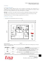
3.3
LED Panel Operations
Set up the system according to the project requirement.
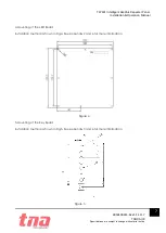
As shown in the figure of the Repeater Panel , Adjust the the dip switch install to configurate the
required pattern. The figure in the lower right of the Repeater Panel
´
s Main board as shown below:
Configuration mode:
Programmable Zone Display a particular zone or device ,and indicate the groups or device
Supervise information.
(1)
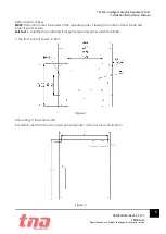
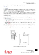
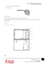
Configuration Preparation
According to the figure 13 configuration. Switched on the 24VDC power to the Repeater
Panel
´
s Main board and the USB connect with computer.
(2)
Configuration and Download
Download the pre-configured data base from TX7810 programming software through a
computer to the control panel. Refer to the TX7810 Defining Tool manual for more details.
NormalWork mode:
In the configuration model is complete, please according to the figure 13 configurate the DIP switch
to normalWork mode, The model for the normal work of Graphic Repeater Panel.
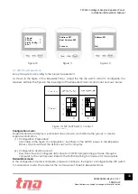
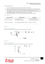
1. Read
2. Write T
3. R/W Config 7
4. Set
Figure 10
Address: 001
Next Address: 002
Success
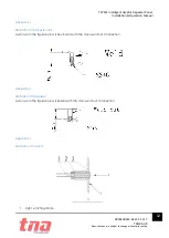
Address: 001
Fail
Figure 11
Figure 12
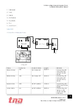
Figure 13: DIP Switch (SW1) connect
explanation