


tams
elektronik
!
!
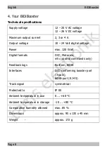
BiDiBooster
English
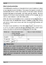
Please note:
Do not block the flow of air through the ventilation slits, otherwise the
booster can overheat.
Risk of fire!
You should never cover the
ventilation slits. When connecting the booster be sure to keep
sufficient distance to other devices, walls, and the like.
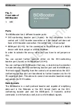
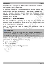
6.1. Using patch cables
The BiDiBooster has – as an alternative to the DCC-conforming booster
port – RJ 45 connectors (C1 and C2) for the connection of the control
unit and additional boosters. When using the RJ 45 connectors data
transfer between the components follows the BiDiB protocol.
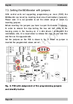
With BiDiBoosters installed at the end of a BiDi-bus line (i.e. with only
one branching RJ 45 cable), you have to mount the terminating
jumpers JP5 and JP6 according fig. 4. In state of delivery JP5 and JP6
are not mounted.
When subsequently connecting additional devices to a BiDi-bus line you
have to dismount the terminating jumpers with the device so far being
installed at the end of the bus line.
Please note:
When not mounting terminating jumpers with the BiDiBooster at one
end of a bus line, interferences in data transfer due to distortion of the
electrical signals possibly occur. With a device with mounted
terminating jumpers but not installed at one end of bus line data
transfer possibly collapses.
In both cases damages at the devices are excluded.
Page 17
Summary of Contents for BiDiBooster
Page 1: ...t a m s e l e k t r o n i k Manual BiDiBooster Item no 40 19507 tams elektronik n n n...
Page 37: ...t a m s e l e k t r o n i k BiDiBooster English Page 37...
Page 38: ...t a m s e l e k t r o n i k English BiDiBooster Page 38...
Page 39: ...t a m s e l e k t r o n i k BiDiBooster English Page 39...


