tams elektronik
Manual
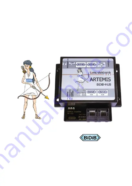
ARTEMIS
Item no. 46-00117
HUB
for a sublevel with 32 nodes
t
a
ms elektronik
n n n
Page 1: ...t a m s e l e k t r o n i k Manual ARTEMIS Item no 46 00117 HUB for a sublevel with 32 nodes tams elektronik n n n...
Page 2: ...ttings 15 6 1 Identify button 15 6 2 Firmware Update 15 7 Operation 16 8 Check list for troubleshooting 18 9 Guarantee bond 20 10 EU declaration of conformity 21 11 Declarations conforming to the WEEE...
Page 3: ...peration Before you start we advise you to read the whole manual particularly the chapter on safety instructions and the checklist for trouble shooting You will then know where to take care and how to...
Page 4: ...ical data output voltage 12 18 V direct voltage DC output current at least 1 A If you use a power supply unit without an integrated cable make sure that the cross section of the supply cable is suffic...
Page 5: ...d impermissibly high humidity and condensation build up can cause serious injury due to electrical shock Take the following precautions to prevent this danger Never perform wiring on a powered module...
Page 6: ...re inattentive and not responsible enough Children under the age of 14 should not be allowed to work with this module In schools training centres clubs and workshops assembly must be supervised by qua...
Page 7: ...the wiring of individual system parts or component groups can be clearly grouped in sublevels The extension of a layout or the addition of additional stationary components is very easy Changes and add...
Page 8: ...ponents The numbers in the figure were dialled in analogy to the addresses that the components receive according to the BiDiB protocol However they are only intended here to clarify the structure Tip...
Page 9: ...on of messages from and to further nodes in a sub level According to the BiDiB specification ARTEMIS transmits all system messages as well as all messages for node management NEW LOST etc ARTEMIS is o...
Page 10: ...mption without connected devices max 25 mA Data Protocols BiDiB Interfaces for BiDiBus Main level 2 RJ 45 sockets Sub level 2 RJ 45 sockets for max 31 further BiDiB nodes Output current for BiDiB comp...
Page 11: ...Connecting ARTEMIS 5 1 Pin assignment 1 Power Voltage supply 12 18 V direct voltage 2 Main level BiDi Bus 3 TERM DCC BiDiB Final jumper DCC BiDiB termination 4 SUB TERM DCC BiDiB Sub level Final jumpe...
Page 12: ...possibly irreparably during commissioning Never connect digital components which are integrated in a conventional digital controller with digital central unit to a power supply unit which is used to s...
Page 13: ...g to the BiDiBus specification patch cables with RJ 45 connections Cat5 cable are provided as bus cables for ARTEMIS These cables are easy and quick to handle and ensure secure connections to the inte...
Page 14: ...ncerned If you subsequently connect one or more devices to the second BiDiB port you must remove the termination jumpers Note If you do not set termination jumpers on a hub installed at one end of the...
Page 15: ...idge in the screen display of the control software press the Identify button on the board The associated BiDiB node is then highlighted on the screen and the LED on the hub flashes 6 2 Firmware Update...
Page 16: ...he operating states Power on fast flickering Device in operation double flashing Registration on the bus was refused Section 8 Identify off no connection to the BiDi bus permanent lighting connected t...
Page 17: ...k fast flashing Bus voltage in the sublevel faulty Section 8 Error messages Power on Identify Message 10 x fast flashing No bootloader found no firmware update possible Contact the Tams Elektronik Hot...
Page 18: ...at the BiDi Bus is rejected Display Double flashing of the LED Identify Possible cause More than 32 components including ARTEMIS are connected to the BiDi Bus in the main level Check the number of com...
Page 19: ...maximum fee for the repair is 50 of the current sales price according to our valid price list We reserve the right to reject the repairing of a module when the repair is impossible for technical or ec...
Page 20: ...lity of the components as well as the function of the parts according to the parameters in not mounted state We guarantee the adherence to the technical specifications when the kit has been assembled...
Page 21: ...led by an authorised electrician Make no changes to the original parts and accurately follow the instructions connection diagrams and PCB layout included with this manual Use only original spare parts...
Page 22: ...t a m s e l e k t r o n i k English ARTEMIS Page 22...
Page 23: ...t a m s e l e k t r o n i k ARTEMIS English Page 23...
Page 24: ...n Information and tips n n http www tams online de n n n Warranty and service n n Tams Elektronik GmbH n Fuhrberger Stra e 4 DE 30625 Hannover fon 49 0 511 55 60 60 fax 49 0 511 55 61 61 e mail model...