


5
Installation
General
All gas water heaters require careful and correct
installation to ensure safe and efficient operation.
This manual must be followed exactly.
1. Read the For Your Safety section in the
beginning of this manual.
2. This unit is not capable of being used as a pool
or spa heater.
3. The Manifold gas pressure is preset at the
factory. It is computer controlled and should
not need adjusted.
4. Suitable for potable water heating only. Well
water or hard water may cause scale problems
that will not be covered by the manufacturer’s
warranty.
5. Maintain proper space for servicing. Install the
unit so that it can be connected or removed
easily.
6. Install so that the electrical power can be
switched off if necessary.
7. Avoid installing in an area with high levels of
dust, sand or debris. Particles may clog the air
vent, reduce fan function, or cause improper
combustion.
8. Do not install the unit where the exhaust vent
is pointing into any opening to a building and
should be at least 3’Ft. from a property fence
or where the noise may disturb your neighbors.
Accessories
Check that all the parts listed below were included
with the unit.
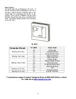
Electrical Connections
The T-KJr. requires a 60 Hz 120 VAC electrical
power supply, and it should be properly grounded
in accordance with the most recent edition of the
National Electrical Code, ANSI/NFPA 70 and any
local codes. In Canada, all electrical wiring to the
heater should be installed in accordance with the
Canadian Electrical Code, CSA C22.1 Part 1, and
any local codes. Do not rely on the gas or water
piping to ground the metal parts of the heater.
CAUTION
:
Label all wires prior to disconnection
when servicing controls. Wiring error can cause
improper and dangerous operation. Verify proper
operation after servicing.
•
A means for switching off the 120 VAC power
to the water heater must be provided.
•
Wire the heater as shown in the wiring
diagram.
•
A green screw is provided in the junction box
for the grounding connection.
Please keep this owner’s manual in a safe
place for future reference. Copies of this
manual are available from TAKAGI-USA
This section is for the installer. The
installer is responsible for the correct
installation of your Flash Water Heater.
For Your Safety:
Only a certified and trained service
technician or qualified plumber may
service or install your product.
Summary of Contents for T-KJr
Page 7: ...6 Wiring Diagram...
Page 24: ...23 Case Burner Gas Manifold...
Page 25: ...24 Water Way...