background image


- 35 - 

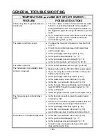
GENERAL TROUBLESHOOTING 

~ TEMPERATURE and AMOUNT OF HOT WATER ~ 

PROBLEM 

POSSIBLE SOLUTIONS 

It takes long time to get hot water at 
the fixtures. 
 

  The time it takes to deliver hot water from the water 

heater to your fixtures depends on the length of 
piping between the two. The longer the distance or 
the bigger the pipes, the longer it will take to get hot 
water. 

  If you would like to receive hot water to your fixtures 

quicker, you may want to consider a hot water 
recirculation system. (p. 40) 

The water is not hot enough.


  Compare the flow and temperature. See the chart 

on p. 51.  

  Check cross plumbing between cold water lines 

and hot water lines. 

  Is the gas supply valve fully open? (p. 29) 

  Is the gas line sized properly? (p. 17) 

  Is the gas supply pressure enough? (p. 16) 

  Is the set temperature set too low? (p. 30,33) 

The water is too hot.


  Is the set temperature set too high? (p. 30,33) 

The hot water is not available when 
a fixture is opened.


  Make sure the unit has 120 VAC / 60 Hz power supply. 

  If you are using the remote controller, is the power 

button turned on? (p. 30) 

  Is the gas supply valve fully open? (p. 29) 

  Is the water supply valve fully open? (p. 29) 

  Is the filter on cold water inlet clean? (p. 34) 

  Is the hot water fixture sufficiently open to draw at 

least 0.5 GPM through the water heater? (p. 30) 

  Is the unit frozen? 

  Is there enough gas in the tank / cylinder? (for Propane models) 

The hot water gets cold and stays 
cold.


  Is the flow rate enough to keep the water heater 

running? (p. 30) 

  If there is a recirculation system installed, does the 

recirculation line have enough check valves? 

  Is the gas supply valve fully open? (p. 29) 

  Is the filter on cold water inlet clean? (p. 34) 

  Are the fixtures clean of debris and obstructions? 

Fluctuation in hot water temperature. 


  Is the filter on cold water inlet clean? (p. 34) 

  Is the gas line sized properly? (p. 17) 

  Is the supply gas pressure enough? (p. 16) 

  Check for cross connection between cold water 

lines and hot water lines. 

Summary of Contents for 910

Page 1: ...each your gas supplier call the fire department Installation and service must be performed by a qualified installer service agency or the gas supplier 910 910 ASME T M50 T M50 ASME On Demand Water Heater Installation Manual and Owner s Guide FEATURING ENDLESS HOT WATER ON DEMAND USAGE COMPACT SPACE SAVING ENERGY CONSERVATION COMPUTERIZED SAFETY NO PILOT LIGHT EASY LINK SYSTEM If you have any quest...

Page 2: ...ION General Included Accessories Warning for Installations Outdoor Installation Indoor Installation Direct Intake Vent System Venting Instructions Gas Supply Gas Pipe Sizing Water Connections Pressure Relief Valve Electrical Connections Remote Controller Connection Pump Control Connections Pump Control Mode Easy Link System Multi Unit System Initial Operation NORMAL OPERATION Normal Operation Flow...

Page 3: ...ption This manual provides information necessary for the installation operation and maintenance of the water heater The model description is listed on the rating plate which is attached to the front cover of the water heater Please read all installation instructions completely before installing this product If you have any problems or questions regarding this equipment consult with the manufacture...

Page 4: ...ture of the 910 T M50 F 3 2 100 120 2 9 125 130 2 6 140 2 4 145 150 2 1 155 185 Example If the set temperature is 120ºF The section s in operation is indicated by the black square s Right combustion section The primary and secondary section will reverse roles every 100 firing cycles or every 12 hours of unit operation Left combustion section or 910 T M50 910 T M50 910 T M50 910 T M50 Depending on ...

Page 5: ...ECTRIC RATING If this unit does not match your requirements do not install and consult with the manufacturer 5 If any problem should occur turn off all hot water taps and turn off the gas Then call a trained technician or the Gas Company or the manufacturer WARNING Water temperatures over 125 ºF 52 ºC can cause severe burns instantly or death from scalding The water temperature is set at 120 ºF 50...

Page 6: ... to surrounding areas As with any water heating appliance the potential for leakage at some time in the life of the product does exist The manufacturer will not be responsible for any water damage that may occur If you install a drain pan under the unit ensure that it will not restrict the combustion air flow The water heater weighs 102 lbs Ensure that any and all support structures whether it is ...

Page 7: ...ert the water heater to a sealed combustion unit Direct venting allows the water heater to draw fresh intake air from the outside The warranty will not cover damage caused to the unit due to installation in a contaminated environment that has not been converted using the direct vent conversion kit 5 Particles from flour aerosols and other contaminants may clog the air vent or reduce the functions ...

Page 8: ...e Do not install this water heater under an overhang less than 3 feet from its top or eaves The area under an overhang must be open to three sides Do not install the water heater vent terminator within 1 ft in the USA of any air intake or building opening and within 3 ft in Canada of any air intake or building opening Refer to p 15 Do not install next to a dryer or any source of airborne debris th...

Page 9: ...he outdoor vent cap must be used when unit is installed outdoor The manufacturer requires the use of its part No 9007677005 TM VC50 5 When installed outdoors the water heater shall be wall mounted or mounted on a stand Locate the water heater in an open unroofed area and maintain the following minimum clearances Make sure power to the unit is turned OFF before changing the dipswitch settings TMP1 ...

Page 10: ...ctly with the outside should have a minimum free area of one square inch per 15 000 BTUH input of the total input rating of water heater in the enclosed area When combustion air is supplied from inside the building an opening communicating with the rest of the dwelling should have a minimum free area of one square inch per 1 000 BTUH input of the total input rating of water heater in the enclosed ...

Page 11: ...ppliance the water heater requires a 5 combustible air supply pipe The intake pipe must be sealed airtight Air supply pipe can be made of ABS PVC galvanized steel corrugated aluminum corrugated stainless steel or Category III stainless steel Change the dipswitch settings to the direct vent system See diagram below Sidewall venting is recommended for the direct vent system The manufacturer recommen...

Page 12: ...ructions when installing the vent pipe 4 Do not common vent this appliance with any other vented appliance Do not terminate vent into a chimney If the vent must go through the chimney the vent must run all the way through the chimney with Category III approved or Special BH vent pipe 5 The maximum length of exhaust vent piping must not exceed 50 ft deducting 5 ft for each elbow used in the venting...

Page 13: ... an unobstructed vent pipe 3 Do not weld the vent pipe to the water heater collar 4 Do not cut the vent collar of the unit 5 The weight of the vent stack must not rest on the water heater 6 The vent must be easily removable from the top of the water heater for normal service and inspection of the unit 7 The water heater vent must not be connected to any other gas appliance or vent stack 8 Avoid lo...

Page 14: ...t or connect any vent from other appliances to the water heater vent Use 5 category III approved or Special BH single or double wall stainless steel vent pipe Wall Roof Rain cap Roof flashing Sidewall vent termination Vertical condensation drain Install according to local codes Vent damper Recommended for freezing weather conditions 36 F and below Vent damper Recommended for freezing weather condi...

Page 15: ... outside corner G Clearance to inside corner H Clearance to each side of center line extended above meter regulator assembly 3 feet I Clearance to service regulator vent outlet 3 feet J Clearance to non mechanical air supply inlet to building or the combustion air inlet to any other application 3 feet 1 foot 4 feet from below or side opening 1 foot from above opening K Clearance to mechanical air ...

Page 16: ...ration Inlet gas pressure must not exceed the above maximum values gas pressure above the specified range will cause dangerous operating conditions and damage to the unit Ensure that any and all gas regulators used are operating properly and are providing gas pressures within the specified range shown above Until testing of the main gas line supply pressure is completed ensure the gas line to the ...

Page 17: ...3 834 771 724 677 630 567 511 440 1 3 307 2 299 1 858 1 559 1 417 1 275 1 181 1 086 1 023 976 866 787 675 2 6 221 4 331 3 465 2 992 2 646 2 394 2 205 2 047 1 921 1 811 1 606 1 496 1 260 10 Length 3 4 Pipe Size Gas Sizing Example Natural Gas 15 Length 1 2 Pipe Size 10 Length 1 2 Pipe Size Furnace 120 000BTU 10 Length 1 Pipe Size Water Heater 380 000BTU 10 Length 1 1 2 Pipe Size Range 65 000BTU 20 L...

Page 18: ...E BY A LICENSED PROFESSIONAL 1 Shut off the manual gas valve on the supply gas line 2 Remove the screw for the pressure port located on the gas inlet of the water heater shown in the diagram to the right 3 Connect the manometer to the pressure port 4 Re open the manual gas valve Check to see that there are no gas leaks Open some of the fixtures that use the highest flow rate to turn on the water h...

Page 19: ...ff switch built in as a standard safety feature called a Hi Limit switch therefore a pressure only relief valve is required This unit does not come with an approved pressure relief valve An approved pressure relief valve must be installed on the hot water outlet The pressure relief valve must conform to ANSI Z21 22 or CAN 1 4 4 and installation must follow local code The discharge capacity must be...

Page 20: ...per operation after servicing 1 The water heater must be electrically grounded Do not attach the ground wire to either the gas or the water piping 2 The water heater requires 120 VAC 60 Hz electrical power supply that is properly grounded A proper disconnect i e on off switch power plug etc controlling the main power to the water heater must be provided for service reasons Must comply with local c...

Page 21: ... are firmly fixed 5 Put the remote wires through the hole on the bottom of the unit casing 6 Connect the remote wires to the remote controller terminal properly No polarity Do NOT jump or short circuit wires or computer will be damaged 7 Replace Front Cover securely 8 Wires used for the remote controller connection must be Minimum 20 gauge wire No polarity Maximum 400 feet long Remote controller t...

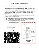
Page 22: ... terminal is essentially only a dry contact An external power supply and relays are required to operate the pump Please make sure the relays are properly rated for the recirculation pump Using the water heater s internal thermistors as a temperature control the recirculation pump will only turn on when recirculation is needed Connect to this terminal This is the pump terminal Power supply for rela...

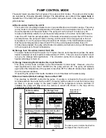
Page 23: ... 5 ON The water heater will heat the water 5 4 F higher than its set temperature unless the water heater is already set at its maximum temperature of 185 F This is to ensure a higher rate of recovery for storage tank applications The circulation pump from storage tank to water heater will always remain on C Energy Conserving Recirculation No 4 and No 5 ON This pump control mode is similar to the R...

Page 24: ...y Link system is limited to 4 units If you connect more than 4 units the first 4 units will work as part of the Easy Link system but the other additional units will only work as individual units The water heater cannot be linked with other different tankless models in the Easy Link system and Multi Unit system CAUTION Easy Link Multi unit System connectors are on each unit s computer board To chan...

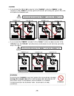
Page 25: ...g LED of all the unit s computer boards display the unit The numbering system automatically allocates the unit to each water heater in the Easy Link system in accordance with the table below CAUTION Unless you change dipswitch No 8 of the PARENT unit to ON the system will not work as an Easy Link system The units will work as individual units PARENT unit Unit 1 CHILD units Unit 2 3 and 4 Wrong dip...

Page 26: ...n cable Do not splice or modify connectors Wrong connection between the PARENT unit and the CHILD 1 unit Wrong connection between the CHILD 1 unit and the CHILD 2 unit Prohibited PARENT unit CHILD 1 unit Communication cable PARENT PARENT Lower bank of Dipswitch OFF ON 1 2 3 4 5 6 7 8 Lower bank of Dipswitch OFF ON 1 2 3 4 5 6 7 8 Connectors Connectors 1 1 2 2 1 1 2 2 PARENT unit CHILD 1 unit Commu...

Page 27: ...00 BTU h to 3 800 000 BTU h An individual cut off switch is recommended for each unit in a multi unit system for the purpose of maintenance The remote controller is not required for the Easy Link system If running the Easy Link system without the remote controller please make sure the dipswitch settings for the temperature outdoor and direct vent settings on ALL the units are set to the same setti...

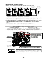
Page 28: ...e multi unit controllers with a remote controller 9007675005 TM MC01 comes with 9007603005 TM RE30 9008300005 TM MC02 comes with 9008172005 TM RE40 The Comunication Cables are included with the 910 T M50 The Cables use 18 gage wire and can be up to 250 ft long all together Easy Link Multi Unit System connectors are on each unit s computer board 7 Seg LED Lower bank of dipswitches Upper bank of dip...

Page 29: ...et Do not use this water heater if any part has been submersed under water Immediately call a qualified service technician to inspect the water heater and to replace any damaged parts CAUTION IF YOU SMELL GAS Do not try to start the water heater Do not touch any electric switch do not use any phone in your building Immediately call your gas supplier from a neighbor s phone Follow the gas supplier ...

Page 30: ...ss the HOT button to set up to 140 F 60 C Increasing temperature above 140 F 60 C Press the HOT button to set 140 F 60 C Press and hold the INFO button and the HOT button for at least 3 seconds The remote will emit a beep and change to 145 F 63 C Press the HOT button to set up to 175 F 80 C or 185 F 85 C 110 115 120 125 130 135 140 145 150 155 160 165 170 175 180 185 WARNING Hot Water temperatures...

Page 31: ...t five seconds And then make sure 1 or 0 is displayed on remote controller 1 is displayed for single units 0 is displayed for Easy Link Multi unit Systems 3 Press the TIME button Make sure OFF and F1 are displayed on remote controller 4 Press the INFO button After make sure OFF blinks 5 Press the HOT button or the COLD button to set display to on 6 Simultaneously press both the BUZZER button and t...

Page 32: ...p power supply The freeze protection system will activate when the surrounding and or outside temperatures drop below 36 5 F 2 5 C In any areas subject to freezing temperatures the manufacturer highly recommends installing the unit indoors In such an installation freezing issues can only occur if cold air enters through the venting into the heat exchanger whether by negative pressures within the i...

Page 33: ...upply to the heater before changing the dipswitch settings Only change the switches with the dark squares The dark squares indicate which direction the dipswitch should be set to DO NOT set to 185ºF if you use your water heater in a recirculation system This will cause damage to the heater and void the warranty To change dipswitch settings for temperatures locate the lower bank of dipswitches to t...

Page 34: ...gh the burner window in the burner assembly located at the middle of the water heater The manufacturer recommends having the unit checked once a year or as necessary by a licensed technician If repairs are needed any repairs should be done by a licensed technician UNIT DRAINING and FILTER CLEANING 1 Close the manual gas shut off valve 2 Turn off power to the unit and then turn on again 3 Wait 30 s...

Page 35: ...30 33 The hot water is not available when a fixture is opened Make sure the unit has 120 VAC 60 Hz power supply If you are using the remote controller is the power button turned on p 30 Is the gas supply valve fully open p 29 Is the water supply valve fully open p 29 Is the filter on cold water inlet clean p 34 Is the hot water fixture sufficiently open to draw at least 0 5 GPM through the water h...

Page 36: ...IONAL PROBLEM POSSIBLE SOLUTIONS Remote controller does not display anything when the power button is turned on Press the ON OFF button If the lamp lights up This is normal When the unit has not operated for five minutes or more the display turns off to converse energy If the lamp does not light Make sure the unit gets power supply Make sure the connection to the unit is correct p 21 An ERROR code...

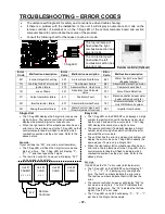
Page 37: ... or left combustion section has an error code the red lamp next to the 7 Seg LED on the central computer board will flash to indicate which combustion section has the error code Refer to the above picture Example If Unit 2 has the 321 error code inlet thermistor The 7 Seg LED on the PARENT unit will display 3 2 1 0 2 displaying only one digit at a time The first 3 numbers indicate the error code T...

Page 38: ...ce technician Forced or attempted repair may result in a fire of explosion D Do not use this water heater if any part has been under water Immediately call a qualified service technician to inspect the water heater and to replace any damaged parts OPERATING INSTRUCTIONS 1 STOP Read the safety information above or in the Owners Manual 2 Turn off all electric power to the water heater 3 Do not attem...

Page 39: ...G The outlet hot water temperature of the water heater is factory set at 120 ºF 50 ºC Use this heater at your own risk The set outlet water temperature can cause severe burns instantly or death from scalds Test the water before bathing or showering Do not leave children or an infirm person in the bath unsupervised DANGER Hot Water Heater temperature over 125 ºF 52 ºC can cause severe burns instant...

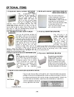
Page 40: ...nnected to any heating system or component s previously used with non potable water where any chemicals were added to the water heating appliances When the system requires water for space heating at temperatures higher than required for other uses a means such as a mixing valve shall be installed to temper the water for those other uses in order to reduce scald hazard potential Water temperature o...

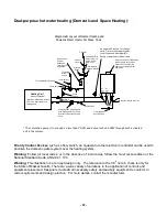
Page 41: ... P T An approved Pressure Only Relief Valve Tie to Location approved by Local Codes and Must Meet BTU Rating of Takagi Model Used Unions 5 Gas Exhaust Vent Discharge Must Comply with Local and State Codes Can Not Be Common Vented with Other Appliances Atmospheric Vacuum Breaker Pump Must Be Sized Properly With Each Application Pump Shall Run 60 Seconds Every 6 Hours Pressure Gauge Apply Correct Th...

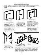
Page 42: ...ltiple unit direct vent sidewall terminations that combine the intake and exhaust into a single penetration space each direct vent termination at least 1 ft away from each other no matter the orientation A direct vent termination must also be at least 2 ft away from an inside corner if the adjacent wall is less than 2 ft of length the minimum required distance away from the inside corner will be e...

Page 43: ...adaptor and any applicable codes 4 Vent cap 9007677005 TM VC50 The vent cap is for outdoor installation with the 910 T M50 water heater The cap is installed on the top of the unit instead of connecting an exhaust vent pipe The cap will prevent any debris that might be in the environment from entering the unit and causing damage or a fire hazard as well as preventing rain or other weather from ente...

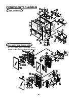
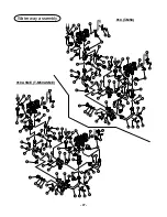
Page 44: ...0 ASME T M50 ASME models share the same components 3 7 6 13 3 11 4 10 1 12 3 3 3 4 2 4 2 3 5 9 8 4 718 709 416 705 707 706 708 704 418 703 715 701 719 113 708 702 710 712 713 711 714 113 711 113 113 716 416 705 707 706 708 704 418 703 709 715 701 719 113 720 721 714 113 113 717 722 723 ...

Page 45: ...07 109 112 106 111 105 113 113 104 103 108 107 113 110 101 114 115 116 113 113 117 707 707 102 121 119 118 707 707 109 112 106 111 105 113 113 104 103 108 107 113 110 101 123 124 126 125 3 123 122 120 705 The 910 T M50 and the 910 ASME T M50 ASME models share the same components ...

Page 46: ...T M50 ASME models share the same components 3 132 133 136 135 137 402 401 403 404 406 407 408 409 410 411 113 412 413 414 415 113 416 405 402 401 403 404 406 407 408 409 410 411 113 412 413 414 415 113 416 405 417 133 134 131 128 130 127 129 137 113 417 138 139 139 138 T M50 ASME 444 445 446 446 447 910 ASME T M50 ASME ...

Page 47: ...406 430 434 3 433 425 438 437 436 435 113 411 420 419 427 426 418 420 428 421 419 419 426 427 411 411 411 419 431 411 418 430 419 420 419 411 424 406 407 419 411 425 427 448 407 406 425 427 411 419 411 419 411 439 440 441 442 443 429 425 421 419 411 406 407 424 429 425 451 407 406 430 434 420 411 418 411 449 421 419 411 450 418 430 3 433 425 438 437 436 435 113 419 411 419 422 422 411 419 427 426 ...

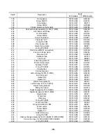
Page 48: ... EKN61 EKK2V EKK2W EKK32 EKK0G 111 112 113 114 115 High voltage igniter cable Pan screw M4X8 Screw M4X10 Manifold assembly with gas valve assembly LP Manifold assembly with gas valve assembly NA Manifold gasket A 319143 039 319143 059 319143 060 319143 263 319143 264 319143 044 EKK2M EW00D EW003 EM302 EM303 EKK2Y 116 117 118 119 120 Manifold gasket B Igniter plate Gas connection plate Pan screw M4...

Page 49: ...ensor 319143 066 319143 086 319143 077 319143 083 319143 092 EKK26 EKH32 EX01H EZM16 EKH33 422 423 424 425 426 Connecting pipe Left cold pipe for 910 T M50 Inlet thermistor Heater 502 Heater 101 319143 251 319143 254 319143 085 319143 333 319143 068 EM285 EM290 EKK38 EX001 EX002 427 428 429 430 431 Heater fixing plate 16 Left hot pipe for 910 T M50 Heater fixing plate 20 Mixing thermistor Right ho...

Page 50: ...EM260 EM271 706 707 708 709 710 Igniter wire Gas valve wire AC100V wire Right and left computer board cover Central computer board cover 319143 231 319143 248 319143 245 319143 183 319143 274 EM257 EM280 EM277 EKH43 EM329 711 712 713 714 715 Multi communication wire Left communication wire Right communication wire Remote controller terminal Wire Cramp 319143 247 319143 234 319143 235 319143 244 31...

Page 51: ... price The manufacturer or its authorized Service Representative may at its sole discretion use new refurbished or reconditioned parts 2 Warranty for all models Unit Year Application Type Heat Exchanger Parts Labor 1 Single Family Domestic Hot Water 15 2 3 5 1 Commercial or Multi Family Domestic Hot Water 10 2 3 Heating 10 3 4 1 Limited Labor Coverage The manufacturer will provide for reasonable l...

Page 52: ... e g water filter water treatment system vent blockage etc Any product installed in an improper environment e g corrosive dusty chemically contaminated excessive lint etc Freeze damage that occurs without taking proper preventive measures as described in the installation manual Condensate damage due to improperly installed or lack of a condensate trap drain Any product not installed in compliance ...

Reviews: