background image

229

Lubrication

Chapter 10

1

2

3

4

5

6

7

8

9

10

11

PT10

3.  

Lubrication

Select TF oil (packed with the machine), or the equivalent (viscosity grade = equivalent to VG20) to 
this one for use.

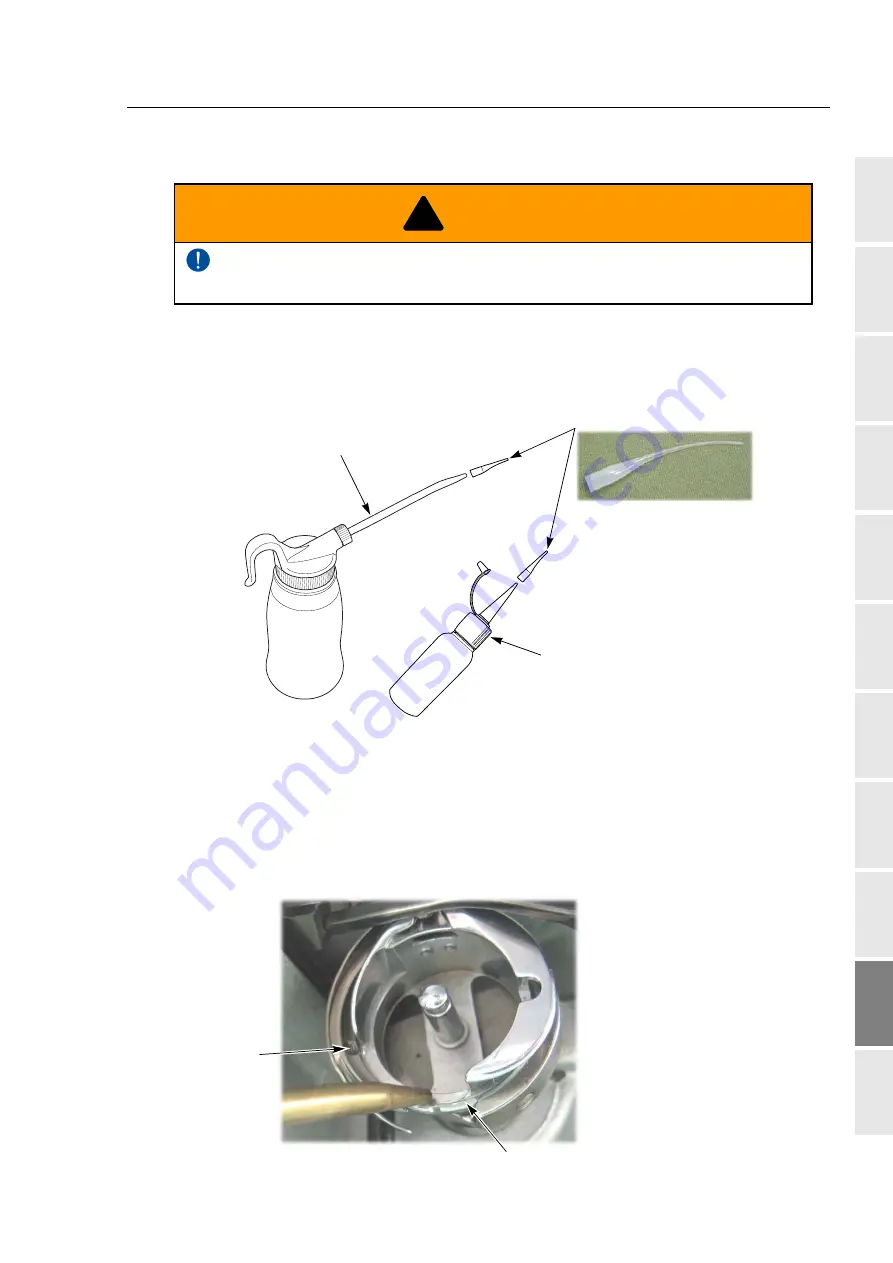
To perform lubrication, use the oiler (accessory) and its nozzle (accessory).

(1) 

Rotary hook

There are 2 lubricating spots (lubrication hole and raceway at the hook). When lubricating to the 
lubrication hole, attach the nozzle (accessory) to the tip of the oiler. Cut the tip of the nozzle 
according to necessary length.

To perform lubrication of the machine, turn off the power switch. You may sustain severe 
injuries due to being entangled by moving machine units.

!

WARNING

In case of single-head 
machine

Nozzle

Oiler

Oiler

Race

Lubrication hole

Lubrication cycle: Once/5 to 6 hours

Summary of Contents for TFMX-IIC

Page 1: ...ow to perform embroidery 1 To turn ON the power 34 2 Thread passing fabric setting 37 3 Registration of a design into the machine memory 41 4 Decision of an embroidery design and the color change sequ...

Page 2: ...TISM...

Page 3: ...event any harm or damage to the person who use this product or other person we describe items that must be surely followed as below Prohibited items Items that may cause electric shock if not observed...

Page 4: ...1 2 TWMX C 15 1 3 TFMX IIC TYPE 2 16 1 4 TFMX L 17 2 How to use each part 18 2 1 Operation panel 18 2 2 Sleep mode key 21 2 3 Emergency stop switch 22 2 4 Needle Base LED Lamp 23 2 5 Jog remote contr...

Page 5: ...Selection 53 4 3 To change color automatically to start operation automatically Auto Color Change AC Auto Start AS 55 5 Decision of the design start position 57 5 1 To check design size and setting co...

Page 6: ...ch length Min Revolution 89 3 2 To set embroidery speed within speed limit section Revolution limit 90 3 3 To decide upper limit value of the maximum speed Max Revolution Limit 91 4 To stop the machin...

Page 7: ...bar case Color change speed 118 8 4 To change travel speed of the frame Frame Travel Speed 119 8 5 To set data of the design automatically after the embroidery is finished Automatic Data Set after fi...

Page 8: ...acement of design when the power is shut off during operation Power resume 158 3 4 To memorize frame origin Frame origin memory 159 3 5 To perform Frame origin memory when the power is turned ON Frame...

Page 9: ...e machine memory by turns from the front The folder is displayed in advance of design 186 Chapter 8 Setting for optional device 1 To make optional device available for use 190 1 1 Sequin Device common...

Page 10: ...n 1 Items that must be followed carefully 226 2 Cleaning 227 3 Lubrication 229 4 Greasing 232 5 Inspection Repair 235 Chapter 11 Appendix 1 Spec of the machine 238 1 1 Power supply specifications 238...

Page 11: ...atic Data Set 103 10 Needle Bar Color 137 1 Maximum RPM 64 2 Total Stitch Counter Design Timer 136 3 Frame Back Frame Forward 146 5 Frame Back All Head Sew 150 6 Preset Halt 92 7 Frame type 152 10 Sto...

Page 12: ...Speed 119 6 Thread Detection 83 9 ATH 80 10 Upper thread lock timing 114 1 Boring 197 2 Sequin 200 Sequin Device III 2 Sequin 204 Sequin Device IV 3 Cording 196 6 Lubrication 192 9 Bobbin Changer 198...

Page 13: ...Limit 133 3 Setting in units of Needle bar 108 6 Frame Limit Setting 96 7 Frame origin memory with the power ON 161 8 Power Resume with the power ON 162 SET F2 1 Max Revolution Limit 91 2 Frame Start...

Page 14: ...To search from the menu key...

Page 15: ...4 5 6 7 8 9 10 11 Chapter 1 Items that must be followed carefully 1 Safety Precautions 2 2 Important warning items for safe operation UL and CSA spec 6 3 Warning labels 9 4 Inspection before starting...

Page 16: ...ions Especially it is dangerous around needle rotary hook take up lever pulley and speed reduction box This machine uses strong magnet The person who is mounted with internal implantable medical elect...

Page 17: ...the power cable plug fully If a metallic part etc touches an electrode in the plug it may cause fire and or electric shock Keep away electrical units from water and chemicals Entry or splashing of th...

Page 18: ...ction and installation of breaker of leak current and leak current relay used for the factory are not correct malfunctioning of the machine may occur Regarding connection of power cord observe the fol...

Page 19: ...y threads do not become disheveled Humidity 30 to 95 RH relative humidity without condensation Ambient temperature 5 to 40 C during operation 10 to 60 C during storage Avoid direct sunlight If the mac...

Page 20: ...in this manual Never operate this appliance if it has a damaged cord or plug if it is not working properly if it has been dropped or damaged or dropped into water Please consult the nearest authorized...

Page 21: ...all controls to the off O position then remove plug from outlet Do not unplug by pulling on cord To unplug grasp the plug not the cord Connect this appliance to a properly grounded outlet only See Gr...

Page 22: ...n sketch B if a properly grounded outlet is not available The temporary adaptor should be used only until a properly grounded outlet can be installed by a qualified electrician The green colored rigid...

Page 23: ...t open the covers There could be danger of electric shock burning or death Persons except the service personnel designated by Tajima should not open the covers When you open the cover turn OFF the pow...

Page 24: ...power switch and wait for four minutes High voltage indication mark Catching mark A B D E A B D D E D D D D D Pay attention not to be caught into the machine Pay attention around needle C Moving part...

Page 25: ...switch and wait for four minutes High voltage indication mark C TWMX C A B Pay attention not to be caught into the machine Pay attention around needle D Moving parts Turn off the switch before access...

Page 26: ...dle might be bent The direction of needle might have been wrong The needle might be broken Rotary hook p 227 Cleaning lubrication might be performed in inadequate frequency Tension base switch p 66 Th...

Page 27: ...13 1 2 3 4 5 6 7 8 9 10 11 Chapter 2 Name and way to use of each part 1 Name of each part 14 2 How to use each part 18...

Page 28: ...ead 11 Needle Base LED Lamp p 23 12 Rotary hook 13 Stand option 1 Thread course 2 Color change system 3 Operation panel p 18 4 X axis motor 5 Start switch p 68 6 Stop switch p 68 7 Power switch p 34 O...

Page 29: ...3 Operation panel p 18 4 X axis motor 5 Stop switch p 68 6 Start switch p 68 7 Power switch p 34 8 Emergency stop switch p 22 9 Head p 66 10 Needle Base LED Lamp p 23 11 Rotary hook 12 Stand option On...

Page 30: ...switch p 68 15 Main shaft motor 1 Thread course 2 Change unit A 3 Change unit B 4 Y axis motor 5 X axis motor 6 Transformer Existence absence differs depending on spec 7 Operation panel p 18 8 Emerge...

Page 31: ...gency stop switch p 22 14 Power switch p 34 15 Main shaft motor 16 Bar switch p 69 1 Thread course 2 Main shaft motor 3 Change unit A 4 Change unit B 5 Operation panel p 18 6 X axis motor 7 Transforme...

Page 32: ...me at high speed It is illustrated as below in this manual It is illustrated as below in this manual 1 Sleep mode key p 22 Switch to power save mode To release press this key again 2 Condition of the...

Page 33: ...memory When connecting the bar code reader commercial item 7 Set key Determine the selected value 8 Frame Travel key p 60 Move the frame manually 6 Escape key E key in this manual The screen will retu...

Page 34: ...es 2 LAN cable Please prepare a commercial item LAN cable is used for connecting a personal computer with the machine Setting of the operation panel is necessary additionally p 193 When you insert the...

Page 35: ...key will be unlit Cancellation will be completed When the following message will be displayed after the cancellation press the SET key Pressing SET key will move the frame to the origin and then retur...

Page 36: ...the operation can be started as usual Specification of the machine Condition after stop How to release EN spec European safety spec The power will be turned OFF 1 Turn the switch clockwise The power...

Page 37: ...ipped to TFMX C TWMX C It is possible to turn ON OFF Needle Base LED Lamp by the switch 2 5 Jog remote controller Option for some models This is a device to move the frame manually Regarding how to us...

Page 38: ...wo seconds or more After trimming threads of all heads the frame will move to the rear Since the movement of the machine after passing the thread differs depending on the switch operation perform any...

Page 39: ...25 1 2 3 4 5 6 7 8 9 10 11 Chapter 3 Screen 1 Screen display 26 2 Message display 31...

Page 40: ...roidered from now 3 Total stitch number of design 4 Current needle bar No 5 Setting of Automatic Offset p 165 With Without 6 Needle bar No selected in each step p 53 7 Setting to return the frame to t...

Page 41: ...ulse is necessary The lock icon will be displayed after design input described below LAN input except Sidekick Design input by using USB memory Data set of the machine memory design 11 Maximum speed p...

Page 42: ...4 Repeat 5 Automatic offset 6 A S after Auto Data Set 10 Needle Bar Color 1 1 Select YES NO by using the jog dial and press SET key To lower the cursor press set key or To return the screen press E ke...

Page 43: ...Stop at Lower D Point Frame Back All head Sew Frame Type 12 13 6 7 8 9 11 Upper thread detection Under thread detection unit Under thread detection step ratio Auto Color Change AC Auto Start AS Auto...

Page 44: ...Screen display 30 Chapter 3 Network 15 15 Network information The screen shown left will be displayed even if Network is set to NO Contents of display differ depending on individual environment...

Page 45: ...hart below depending on the saving format T3 T2 T of the design About T2 One design consists of three types of file TAJIMA_W CT0 TAJIMA_W DGF TAJIMA_W TBF Saving format Indication in personal computer...

Page 46: ...of design 5 Automatic Offset The message shown left will be displayed only when the machine reads condition data at 2 1 This message is displayed when performing data set Design start position means t...

Page 47: ...N the power 34 2 Thread passing fabric setting 37 3 Registration of a design into the machine memory 41 4 Decision of an embroidery design and the color change sequence 50 5 Decision of the design sta...

Page 48: ...of the power switch depending on the model 1 1 1 TFMX C TWMX C 1 1 2 TFMX llC TYPE 2 Do not turn ON the machine power in the state that the USB memory is connected to the operation panel except when...

Page 49: ...his type can be locked When locking ON OFF ON T R I P P E D Handle Groove Lock plate Commercial 1 Turn the handle toward direction A to the position of the groove 2 Push the lock plate to the directio...

Page 50: ...lar BIOS Press DEL to set up Software version installed in the machine will be displayed Now System Loading 40 Windows CE net Microsoft T MX C Press SET The frame will move and return to the original...

Page 51: ...ead does not pass to each section correctly it could cause trouble such as the deterioration of embroidery or the thread breakage etc Pass the thread correctly referring to the figure below 1 Place th...

Page 52: ...38 Chapter 4 3 Put the thread into the groove of the tension stud Indicated by an arrow 4 To perform threading through the spiral tube use the threader accessory Groove Groove Threading Spiral tube T...

Page 53: ...tension would be affected badly Return the adjusting lever to the original position after passing the thread Otherwise thread breakage would be caused or the thread tension would be affected badly Up...

Page 54: ...ient works by reducing the thread breakage it is important to stretch the fabric correctly on the embroidery frame Fix fully stretched fabric without any wrinkle Cap frame Tubular goods frame Border f...

Page 55: ...e total of folders and designes that can be read per 1 layer directory is 255 designs b Folder c Design 4 Data Input USB A Cap frame Border frame T2 TCF T3 TBF T DST T DST a b c Folders and designs sa...

Page 56: ...ion differs depending on the storing place of the design a Design in folder b Design on screen Pressing SET will display the folder in the first level or design To return to the original level press E...

Page 57: ...5 To move frame to the design start position After that proceed to To decide color change sequence Needle Bar Selection p 53 When performing this operation do not put your hands etc on the machine ta...

Page 58: ...into the design data TCF DG ML by Pulse is necessary Besides when the data of the design TCF in which the message is written is set if i key is pressed the detail of the message can be checked Display...

Page 59: ...39 Software sold separately DG ML by Pulse and setting of IP address are necessary to perform thisoperation For details consult the distributor 3 2 1 Screen 3 2 2 How to operate not to use bar code re...

Page 60: ...e frame to the design start position After that proceed to To decide color change sequence Needle Bar Selection p 53 When performing this operation do not put your hands etc on the machine table Movin...

Page 61: ...work setting is YES p 193 3 Connect the bar code reader to the USB port of the operation panel p 20 4 Set to the main screen 5 Read the bar code Condition data Color change sequence is also read autom...

Page 62: ...the power is turned OFF and ON The pre read design requires the following conditions a The design which can be performed pre reading is one design only b When bar codes are read plural times during op...

Page 63: ...e troubles with the following procedure If these troubles are not solved please consult the distributor Error code No BC1 Press E key Resetting error Design data transmission to Spooler Rereading of t...

Page 64: ...memory can be displayed b Folder Folder name can be changed p 178 c Design registered in the machine memory 1 Data Input Memory A Group 1 Group 2 Group 3 Group 5 Group 4 4 c b a The capacity of the m...

Page 65: ...to embroider 1 To open screen 2 To select a design The operation differs depending on the storing place of the design a Design in folder b Design on screen Pressing SET will display the design in the...

Page 66: ...ition When performing this operation do not put your hands etc on the machine table Moving frame could injure you Pressing SET will move the frame then data set will be completed When the movement of...

Page 67: ...tion is called step 2 Step display differs depending on with without setting of Auto Color Change AC When Sequin device III is mounted the following display will appear c Offset mark The illustrated e...

Page 68: ...een 2 To select needle bar No to use at step 1 Set also other needle bar No in the same procedure 4 2 3 How to operate to insert offset mark The following is an example of inserting the offset mark be...

Page 69: ...O will disable the following settings b Setting to start operation automatically after color change YES To perform NO Not to perform Selecting NO will disable the following settings c Setting to start...

Page 70: ...e This is an example of setting in the following conditions Auto Color Change AC Auto Start AS Automatic Start at the same color 1 To open screen 2 Auto Color Change AC 3 Auto Start AS 4 Automatic Sta...

Page 71: ...n Stitch Counter Function Stitch length Design counter Step Offset Data conversion Rotation Reverse Repeat M Repeat 0 88 4 0 0 59 6 59 2 From Start Point 1 8 3 10 5 7 2 7 8 4 80 3 3 130 0 pp 0 0 G0041...

Page 72: ...operate The following is an example of lowering the needle bar 1 To open screen 2 To lower needle bar Up To raise needle bar Down To lower needle bar When performing this operation do not put your ha...

Page 73: ...the screen TAJIMA_W 14117 Main screen The current frame position is displayed by the numerical value mm The frame position is based on the frame origin The code means the frame travel direction X Y 15...

Page 74: ...uttle a Switch to the main screen Press E key plural times to switch to the main screen b To decide Frame Travel direction Press E key to decide the frame travel direction When performing this operati...

Page 75: ...huttle high speed The frame will move 3 To use the Jog remote controller some models only a Switch to the main screen Press E key plural times to switch to the main screen b To move frame to the desig...

Page 76: ...c on the machine table Moving frame could injure you 1 2 3 4 5 6 7 Start point of design The number in the left figure indicates the orbit of the frame After completion of trace embroidering from that...

Page 77: ...n after temporary stop b Code No 225 will be displayed Press E key c Move the frame to the design start position d Perform tracing again To suspend tracing follow the procedure below a Suspend the ope...

Page 78: ...w to operate The following is an example when setting the maximum speed to 950 1 To open screen Stitch length Embroidery speed Up to 4 0 mm Maximum speed A in the right figure 4 1 mm to 11 9 mm Automa...

Page 79: ...peed Selection of the value exceeding Max Revolution Limit is not possible To change the maximum speed during operation of the machine turn the jog dial the jog shuttle While turning the jog dial the...

Page 80: ...ally The switch operation during working of the machine is invalid Even if the switch operation is performed it will become effective after the machine stops Tension base switch Green Red Unlit Lit OF...

Page 81: ...e This lever will suspend the head mechanically 3 Middle thread guide adjusting lever Move the lever so that the screw faces the front ON Ready to embroider OFF Embroidery is suspended Switching Lever...

Page 82: ...the start switch 2 To stop the machine press the stop switch 3 To start slow operation keep on pressing the start switch Releasing it will start normal operation Before starting the machine pay enoug...

Page 83: ...function will return the frame to the direction of stitches returning in the state that the needle bar is stopped The frame will be returned when thread breaks and the repair stitches will be performe...

Page 84: ...TWMX C TFMX IIC TYPE 2 Press the stop switch once TFMX L Move the bar switch to the left and return it immediately TFMX C TWMX C TFMX IIC TYPE 2 Keep on pressing the stop switch The frame will return...

Page 85: ...of stitches being set p 149 TFMX L Move the bar switch to the left and hold it in that position The frame will return stitch by stitch up to 10 stitches For 11 stitches or more the frame will return a...

Page 86: ...switch The frame will advance stitch by stitch up to 10 stitches For 11 stitches or more the frame will advance at high speed 1 To stop the machine press the stop switch again 1 For 11 stitches or mor...

Page 87: ...ge indicator lamp lights in red or blinks in green Lit in red Upper thread has broken Blinking in red Under thread has broken 2 Code No number indicating stop factor will be displayed on the operation...

Page 88: ...hread breakage and the head without thread breakage Head with thread breakage The machine restarts embroidering from the position where Frame Back stopped 1 in the figure below As a result repair stit...

Page 89: ...of the head to the Top once when you release the switch it will return to the original position 7 4 Completion of embroidery Destination of the frame movement differs depending on setting of the mach...

Page 90: ...Embroidery starts 76 Chapter 4...

Page 91: ...idery speed 89 4 To stop the machine 92 5 To change the direction and the size of the design 98 6 To embroider the same design repeatedly 100 7 To adjust finishing of embroidering 104 8 To increase em...

Page 92: ...needle bar is changed color to the 5th needle 1 To open screen 2 To select needle bar No and execute color change Current needle bar No When performing this operation do not put your hands etc around...

Page 93: ...thread trimming To trim thread Under thread To trim under thread only Excluding TFMX C TWMX C When performing this operation do not put your hands etc near the needle Moving up down of the needle bar...

Page 94: ...g due to short of remaining length of upper thread select the value of When N is displayed the value differs in each needle bar Regarding the setting of needle bar unit refer to detailed page p 108 c...

Page 95: ...pulling out g Stitch length of f described above When N is displayed the value differs in each needle bar p 108 Triangle 1 2 3 T0 One reciprocation 1 2 1 Triangle one reciprocation 1 3 4 5 2 T1 Two r...

Page 96: ...to 2 and inching after ATH is set to 3 1 To open screen 2 To trim thread automatically 3 To select thread trim length When N is displayed changing N to a value will set the detecting sensitivity in al...

Page 97: ...ted after upper thread breaks three times continuously The relationship between the number of detecting times and sensitivity is shown as follows b Setting how many consecutive times of detection of U...

Page 98: ...tecting ratio and sensitivity is shown as follows 2 3 2 How to operate The following is an example that the number of upper thread breakage detecting times is set to 2 and the number of under thread b...

Page 99: ...he number of jump code without editing the design 2 4 1 Screen a Number of consecutive jump codes NO Not effected 1 to 9 Number of consecutive jump codes b How to move frame to next stitch A Batch B A...

Page 100: ...Data to move the frame in X axis direction When the value is 8 the frame travel amount is 0 8 mm c Function Code p 243 It is the code to indicate the role of the stitch d Y data Data to move the fram...

Page 101: ...stitch No to perform thread trimming 4 To select Insert and decide 5 To select Modify to move the cursor 6 To select ATH 7 To decide Press SET key three times TBF 3 6 7 6 7 20 12 0 Stitch 20th stitch...

Page 102: ...t timing is set to 5 degree 1 Set to main screen 2 Press F2 key while pressing SET key 3 Press F2 key 4 To select ATH drive start timing Timing to start moving thread trimming knife Value is of main s...

Page 103: ...ry speed by stitch length Min Revolution 3 1 1 Screen 3 1 2 How to operate The following is an example that Low Speed R P M is set to 550 rpm 1 To open screen 2 To select Low speed R P M Maximum speed...

Page 104: ...the following function code 3 2 1 Screen 3 2 2 How to operate The following is an example that the maximum speed of the section between the function codes Low_S to Low_E is set to 700 1 To open screen...

Page 105: ...operate The following is an example that Max Revolution Limit is set to 950 1 Set to main screen 2 To press F2 key while pressing SET and press SET further 3 To cancel the password Regarding cancelin...

Page 106: ...s Display of 1D2 d The machine will stop when counting reaches the number of set stitches Display of OIL When automatic lubrication system is set to YES it will not be displayed e The machine will sto...

Page 107: ...ore needle bar hits the frame Software Frame Limit 4 2 1 Screen a Software Frame Limit YES To set NO Not to set b Frame Type selected now It is impossible to change Software Frame Limit is memorized i...

Page 108: ...reen 2 To make software frame limit effective 3 To decide P1 Point 1 4 To decide P2 Point 2 When performing this operation do not put your hands etc on the machine table Moving frame could injure you...

Page 109: ...uck in the material at the end of embroidery This function is effective for embroidering to consecutive design using AFC option mainly 4 3 1 Screen 4 3 2 How to operate The following is an example tha...

Page 110: ...spec machine 4 4 1 Screen 4 4 2 How to operate The following is an example that the frame is stopped at Frame Limit 1 Set to main screen 2 To press F1 key while pressing SET Stop at Frame Limit YES T...

Page 111: ...To stop the machine 97 Chapter 5 1 2 3 4 5 6 7 8 9 10 11 3 To press F1 key 4 To make Frame Limit setting effective 6 Frame Limit Setting NO YES 6 7 6 7...

Page 112: ...etting contents here will be added in a design So when you embroider this design next time setting again will be unnecessary 5 1 1 Screen a Horizontal X scale ratio b Vertical Y scale ratio c Rotating...

Page 113: ...4 5 6 7 8 9 10 11 5 1 2 How to operate The following is an example that horizontal scale ratio and vertical scale ratio are set to 120 1 To open screen 2 To select horizontal scale ratio 3 To select v...

Page 114: ...etting again will be unnecessary 6 1 1 Explanation on the screen a Repeat method The illustration below is an example that the priority embroidery direction is vertical b Number of repeats in horizont...

Page 115: ...played only and cannot be changed 6 1 2 How to operate The following is an example that repeat pattern pb the number of repeats in horizontal 3 interval in horizontal 60 the number of repeats in verti...

Page 116: ...tical 6 To select interval in vertical mm 7 To select priority embroidering direction To cancel the setting of repeat set the number of repeats in horizontal and the number of repeats in vertical to 1...

Page 117: ...y when Auto Start AS is set to YES p 55 6 2 1 Screen 6 2 2 How to operate The following is an example that Automatic Start after Automatic Data Set is set 1 To open screen 2 To set automatic start aft...

Page 118: ...hes are executed 7 1 1 Explanation on the screen a Correcting value in horizontal b Correcting value in vertical a 4 Backlash F1 0 0 0 0 X 0 5 0 5 mm Y 0 5 0 5 mm b 0 5 mm Original stitch Stitch after...

Page 119: ...Screen a Applicable range Whole All satin stitches in the design are targets Part Satin stitches of the section surrounded by satin stitch codes Satin_S to Satin _E are targets It is necessary to add...

Page 120: ...er 5 7 2 2 How to operate The following is an example that applicable range is set to part and expansion amount is set to 0 4 1 To open screen 2 To select applicable range 3 To select adding amount 3...

Page 121: ...jump automatically when a stitch exceeding a set value is given When a value is 4 0 the machine will jump automatically if stitches of 4 1 mm and more are given When the setting of frame type is set...

Page 122: ...hine set Upper and Under Unit to 0 1 2 3 4 To stop if upper thread is broken When selecting 3 the thread breakage will be detected after upper thread breaks three times continuously The relationship b...

Page 123: ...ween the number of detecting times and sensitivity is shown as follows e Sensitivity of d described above Set sensitivity of d Change this value according to the type of fabric and thread to use It en...

Page 124: ...mple that the needle bar No is set to 3 the maximum speed is set to 950 and the upper thread breakage detecting sensitivity is set to 3 1 Set to main screen 2 To press F1 key while pressing SET 3 To p...

Page 125: ...r thread breakage detecting times 7 5 To delete tiny stitch Cleanup This function removes tiny stitch that causes thread breakage and it is added to the next stitch This function has an effect to decr...

Page 126: ...e stitch length to remove is set to 0 5 1 To open screen 2 To select a design 3 To select stitch length to remove and execute The original design will be overwritten after removing fine stitches Back...

Page 127: ...ain screen 2 Press F2 key while pressing SET key 3 Press F2 key 4 To select Frame Start Timing Timing to start moving the frame Value is of main shaft angle To change this value consult the distributo...

Page 128: ...stment when the edge of upper thread remains on the fabric after thread trimming When the edge of upper thread is still highly visible set to B or C 7 7 2 How to operate The following is an example th...

Page 129: ...general due to characteristic of the machine However this aptitude may not be applicable depending on setting condition of other items and or machine condition c Stitch in crosswise direction of aroun...

Page 130: ...To adjust finishing of embroidering 116 Chapter 5 3 Press F2 key 4 To select stitch in horizontal direction of around 4 mm 3 Frame Drive Adjustment 6 7 6 7 1 6 7 6 7...

Page 131: ...p 80 8 1 1 Screen 8 1 2 How to operate The following is an example that the number of Start Inching is set to 3 1 To open screen 2 To select number of lowering needle bar at slow operation 8 2 To col...

Page 132: ...TWMX C only When sequin device III is equipped the machine does not have this function 8 3 1 Screen 8 3 2 How to operate The following is an example that Color Change Speed is set to High 1 Press the...

Page 133: ...nction targets at origin return of the frame and or offset travel 8 4 1 Screen 8 4 2 How to operate The following is an example that Frame Travel Speed is set to 100 mm sec 1 To open screen 2 To selec...

Page 134: ...Delete the design automatically after finishing the embroidery It is selectable only when a is set to NO YES To perform NO Not to perform 8 5 2 How to operate The following is the example of Not to pe...

Page 135: ...ncrease embroidering efficiency 121 Chapter 5 1 2 3 4 5 6 7 8 9 10 11 4 To select NO Not to perform Automatic Data Set of the design 5 To select YES Delete the design automatically NO 6 7 6 7 YES 6 7...

Page 136: ...m c Function Code p 243 It is the code to indicate the role of the stitch d Y data Data to move the frame in Y axis direction When the value is 4 the frame travel amount is 0 4 mm 9 1 2 How to operate...

Page 137: ...select stitch No by using search function refer to the detail page p 124 b To select the stitch No by the jog dial jog shuttle follow the explanation below To select stitch No by using the jog dial j...

Page 138: ...effective 4 To search stitch by function code 5 To complete the search and select Modify Pressing SET key will search the stitch including a function code Color Pressing SET key further will search th...

Page 139: ...To edit design 125 Chapter 5 1 2 3 4 5 6 7 8 9 10 11 6 To edit X data 7 To edit Y data 8 To modify the function code 9 Decide the modification 0 6 7 6 7 0 6 7 6 7 Jump 6 7 6 7 Are you ready 6 7 6 7...

Page 140: ...243 It is the code to indicate the role of the stitch d Y data Data to move the frame in Y axis direction When the value is 4 the frame travel amount is 0 4 mm 9 2 2 How to operate The following is an...

Page 141: ...nction refer to the detail page p 128 b To select the stitch No by the jog dial jog shuttle follow the explanation below To select stitch No by using the jog dial jog shuttle 3 To select stitch No to...

Page 142: ...4 To search stitch by function code 5 To complete the search and select Insert Pressing SET key will search the stitch including a function code Color Pressing SET key further will search the next st...

Page 143: ...r 5 1 2 3 4 5 6 7 8 9 10 11 6 To execute insertion 7 To select Modify to move the cursor 8 To select Jump 9 To decide insertion Press SET key three times Are you ready 6 7 6 7 Modify 6 7 6 7 Jump 6 7...

Page 144: ...8 mm c Function Code p 243 It is the code to indicate the role of the stitch d Y data Data to move the frame in Y axis direction When the value is 4 the frame travel amount is 0 4 mm 9 3 2 How to ope...

Page 145: ...refer to the detail page p 131 b To select the stitch No by the jog dial jog shuttle follow the explanation below To select stitch No by using the jog dial jog shuttle 3 To select stitch No to delete...

Page 146: ...ect Delete 6 To decide deletion Pressing SET key will search the stitch including a function code Color Pressing SET key further will search the next stitch When there is no selected function code dis...

Page 147: ...ng Manual 10 1 1 Screen 10 1 2 How to operate The following is an example that the password is changed from 0000 to ZY98 1 Set to main screen 2 Press F1 key while pressing SET key and press SET key fu...

Page 148: ...a To select 0 b To input the remaining password 0 0 0 in the same procedure c To decide 4 To input password after change a To select Z b To select Y c To select the remaining password 9 8 in the same...

Page 149: ...g procedure after canceling the password 10 2 1 Screen 10 2 2 How to operate The following is an example that the password 0000 is cancelled 1 To select the password 0 2 To select the remaining passwo...

Page 150: ...en shows an example of 50 minutes and 8 seconds Counting continues even during sleep mode and turning OFF the power Embroidery time will be reset in the following conditions When the current embroider...

Page 151: ...ll display an image similar to the embroidered product 11 2 1 Screen 11 2 2 How to operate The following is an example that the needle bar No 1 set to red 1 To open screen 2 To select the needle bar N...

Page 152: ...Set to main screen 2 To press B key while pressing SET 3 To press B key 4 To select Yes YES Display the setting color when making the design When the information about the setting color is not includ...

Page 153: ...rate The following is an example that the software version is checked 1 Set to main screen 2 To press F4 key while pressing SET 3 Since SET F4 screen will be displayed check the version of the softwar...

Page 154: ...xample that the language is changed to English 1 Set to main screen 2 To press F4 key while pressing SET 3 To press F4 key 4 To select language SET F4 2 Date and Time 3 Machine Type 4 Machine Number 5...

Page 155: ...lways NO Not to fix the main shaft motor always while the main shaft stops Always NO will be displayed in TFMX C TWMX C only b Current main shaft angle When you desire to check the main shaft angle se...

Page 156: ...5 11 6 2 How to operate The following is an example that the main shaft motor is set to not to fix 1 Set to main screen 2 Press F3 key while pressing SET key and press SET key further 3 To select not...

Page 157: ...lowing message 11 7 1 Screen 11 7 2 How to operate The following is an example when the screen of Read Condition data file is not displayed 1 Set to main screen 2 To press A key while pressing SET key...

Page 158: ...Functions that must be remembered 144 Chapter 5...

Page 159: ...ame Frame Back to advance the frame Frame Forward 146 2 Necessary works after replacing the frame 152 3 To return the frame to the original position 156 4 To return the frame to the design start posit...

Page 160: ...etting frame forward 1 To open screen 2 To select FF Frame Forward 3 Frame Back Frame Forward C FB NO 1 39628 FB FF Stop code Stitches FB FF Stitch Unit Stitch Counter 1 3 5 Switching of FB Frame Back...

Page 161: ...ward by specifying the number of stitches NO Not to perform 1 to end stitch To perform to perform Frame Back or Frame Forward for the number of stitches 1 2 2 How to operate The following is an exampl...

Page 162: ...de 1 2 3 How to operate The following is an example of specifying the number of stitches and executing frame forward 1 To open screen 2 To select FF Frame Forward Pressing SET key will move the frame...

Page 163: ...ccessive due to the operation of frame back frame forward by the stop switch or the bar switch 1 3 1 Explanation on the screen 1 3 2 How to operate The following is an example of setting the frame fee...

Page 164: ...ther the machine stops at the position just before All Head Sewing Start Point or not 1 4 1 Explanation on the screen a Frame Back All head Sew ALL 0 9 b The machine stops at the position just before...

Page 165: ...llowing is an example of setting All Head Sewing Start Point to 3 and setting to Stop at the position just before All Head Sewing Start Point 1 To open screen 2 To select All Head Sewing Start Point 3...

Page 166: ...lution limit will be the following value High speed 700 rpm Low speed 300 rpm Moreover when selecting X ext W Auto jump will be set forcibly and the setting range will be 2 0 to 4 0 mm Initial value i...

Page 167: ...1 To open screen 2 To select the frame 3 To execute Frame Origin Memory The below message will not be displayed for L spec machine The following message will be displayed only when Frame origin memor...

Page 168: ...sition and it might cause the damage of the parts The center of embroidery space Upper right position Pressing SET key will move the frame Frame origin memory YES SET Code No 5C1 will appear Move the...

Page 169: ...the design to set data conversion 2 2 1 Explanation on the screen 2 2 2 How to operate The following is an example of setting of design rotation by 180 degree to To perform 1 Set to main screen 2 To...

Page 170: ...stopping the machine in the middle of embroidery 3 1 1 Screen 3 1 2 How to operate The following is an example of executing manual offset 1 To open screen 2 To perform manual offset To return the fram...

Page 171: ...position and starting the operation 1 Set to main screen 2 Press F2 key while pressing SET key 3 Press F2 key 4 To return the frame by operating the bar switch or the start switch and start the operat...

Page 172: ...w to operate The following is an example of executing Power resume 1 Set to main screen 2 Press F2 key while pressing SET key 3 Press F2 key When performing this operation do not put your hands etc ne...

Page 173: ...ate of power OFF or during sleep mode in such a case as changing frame 2 After installation of software 3 When frame driver is changed 4 When frame type is changed When a frame origin is wrong the fol...

Page 174: ...to L spec machine Also it is possible to perform setting only when Frame limit setting is set to Yes This is the setting to display the message and perform Frame origin memory when the power is turned...

Page 175: ...To press F1 key while pressing SET 3 To press F1 key 4 To display the message Display of the message to urge frame origin memory YES To display NO Not to display Even if the power is turned ON again i...

Page 176: ...ting to display the message and perform power resume when the power is turned ON 3 6 1 Screen 3 6 2 How to operate The following is an example of displaying the message to suggest power resume 1 Set t...

Page 177: ...the machine 4 1 1 Screen 4 1 2 How to operate The following is an example of executing design start position return 1 To open screen 2 To execute design start position return To return the frame to t...

Page 178: ...Automatic offset is set the frame will return to an offset start position p 165 4 2 1 Screen 4 2 2 How to operate The following is an example of setting Automatic origin return 1 To open screen 2 To m...

Page 179: ...he frame will pass from the offset start position A through the offset middle position B and move to the design start position C 2 When embroidery is finished the frame will pass from the design end p...

Page 180: ...t Start position A To cancel setting for Automatic offset set values of OF1 and OP2 described above to 0 When performing this operation do not put your hands etc on the machine table Moving frame coul...

Page 181: ...point D to the offset start position A through the offset middle position B After performing works for applique here the frame will move to the color change point D through the offset middle position...

Page 182: ...te The following is an example of inserting the offset mark between step 2 and step 3 1 To open screen 2 To select step to insert offset mark 3 To insert offset mark To delete offset mark 2 Needle Bar...

Page 183: ...c offset is set The offset middle position is not passed 5 3 1 Screen 5 3 2 How to operate The following is an example of executing offset return 1 To open screen 2 To execute offset return To return...

Page 184: ...witch will set position the table offset position to where the frame moves 6 1 1 Screen 6 1 2 How to operate The following is an example of setting the table offset position 1 Set to main screen 2 Pre...

Page 185: ...171 1 2 3 4 5 6 7 8 9 10 11 Chapter 7 Function concerning storing and deleting of design 1 Design stored in the machine memory 172 2 Design saved in USB memory 184...

Page 186: ...1 1 2 How to operate The following is an example of deleting a selected design 1 To open screen 2 Select a deleting method 3 To select and decide a design 8 Memory Delete A One All One How to delete a...

Page 187: ...2 To select a design The operation differs depending on the storing place of the design a Design in folder Group 1 Group 2 Group 3 Group 4 Group 5 4 Move a design Group 1 Group 2 Group 3 Group 4 Grou...

Page 188: ...1 Screen The screen will be switched 3 6 7 6 7 Group 3 6 7 6 7 Are you ready 6 7 6 7 Group 1 Group 2 Group 3 Group 4 Group 5 5 Copy a design Group 1 Group 2 Group 3 Group 4 Group 5 5 Copy a design Pa...

Page 189: ...design and storing it in the folder Group 3 1 To open screen 2 To select a design The operation differs depending on the storing place of the design a Design in folder b Design on screen 3 Select a de...

Page 190: ...0 1 To open screen 2 To select a design The operation differs depending on the storing place of the design a Design in folder 6 Changing design name G001 Group 1 Group 2 Group 3 Group 4 Group 5 6 Chan...

Page 191: ...reen 3 To change file name a To return the cursor to the top of the file name b To select A c To select 1 d To select 0 e To select Enter and decide The screen will be switched Press SET key four time...

Page 192: ...the folder name from Group 1 to Design1 1 To open screen 2 To select a folder The screen will be switched 7 Changing folder name Group 1 Group 1 Group 2 Group 3 Group 4 Group 5 7 Changing folder name...

Page 193: ...urn the cursor to the top of the folder name b To select D c To set to make small letters possible to be input d To select e e To select s f To select the remaining character ign 1 similarly g To sele...

Page 194: ...It gives priority to updated time When selecting Time perform the setting of the following b File name Give priority to the file name of the design When selecting File perform the following setting c...

Page 195: ...owing is an example of setting sort of the design giving the priority to Time and to New Old 1 Set to main screen 2 To press A key while pressing SET key and press SET key further 3 To select priority...

Page 196: ...ave This operation requires input of the password 1 7 1 Screen 6 USB Save Password Group 1 Group 2 Group 3 Group 4 Group 5 6 USB Save Selection of design to store into the USB memory 6 USB Save Saving...

Page 197: ...g canceling method refer to the detail page p 135 4 To select a design The operation differs depending on the storing place of the design a Design in folder b Design on screen c To select Enter and de...

Page 198: ...rate The following is an example of deleting a design 1 To set USB memory 2 To open screen 3 To select a design The operation differs depending on the storing place of the design a Design in folder 7...

Page 199: ...4 5 6 7 8 9 10 11 b Design on screen 4 To delete Pressing i key will display the design confirmation screen p 29 To return to the original screen press E key T3 G001 TCF TAJIMA_W 14117 6 7 6 7 G001 TC...

Page 200: ...priority to updated time When selecting Time perform the setting of the following b File name Give priority to the file name of the design When selecting File perform the following setting c b Sorting...

Page 201: ...e of setting sort of the design giving the priority to Time and to New Old 1 To set USB memory 2 Set to main screen 3 To press A key while pressing SET key 4 To press A key 5 To select priority to sor...

Page 202: ...Design saved in USB memory 188 Chapter 7...

Page 203: ...189 1 2 3 4 5 6 7 8 9 10 11 Chapter 8 Setting for optional device 1 To make optional device available for use 190 2 To set details of optional device 200 3 Functions concerning optional device 206...

Page 204: ...device equipped to left side Not to use the device SQ High speed Sequin device SQ3 Sequin device III Up down by motor type When you select SQ3 in TFMX C TWMX C color change speed will become 1 2 of n...

Page 205: ...4 5 6 7 8 9 10 11 3 To press F3 key 4 To select type of sequin Proceed to the following operation continuously When selecting SQ3 proceed to 2 1 Sequin Device III p 200 When selecting SQ4 proceed to 2...

Page 206: ...hook When counting reaches the number of set stitches the machine will lubricate the rotary hook recommended value 50000 c Lubricating cycle to inside of the arm When counting reaches the number of se...

Page 207: ...on 1 3 1 Screen 1 3 2 How to operate The following is an example of inputting a design from DG ML by Pulse with Normal 1 Set to main screen 2 To press F3 key while pressing SET NO Not to connect Norma...

Page 208: ...side R Equipped to right side L R Equipped to left and right side NO Not to equip b Insert jump before feeding material Setting whether or not to insert a non data jump code automatically before feedi...

Page 209: ...perform NO Not to perform 1 4 2 How to operate The following is an example that the device is equipped to the left side and Jump is set to To insert before feeding out beads 1 To open screen 2 To equi...

Page 210: ...n a Use of the device YES To use NO Not to use b Equipped needle bar position 1 st needle Equipped to the right side 12 th needle Equipped to left side in case of 12 needle machine The last needle wil...

Page 211: ...1 Screen a Setting of Boring b Needle bar No equipped with device Value Device Frame Travel 1 1 When switching to boring the frame will move by 12 mm in vertical direction Scale up down rotation reve...

Page 212: ...To select the needle bar No 1 7 Bobbin changer This is a setting for making Bobbin changer UBC II available for use For details of the device refer to the separate manual UBC II 1 7 1 Explanation on...

Page 213: ...To make optional device available for use 199 Chapter 8 1 2 3 4 5 6 7 8 9 10 11 2 To use Bobbin changer YES 6 7 6 7...

Page 214: ...s about 1 0 to an external diameter of chip as a rough standard c Insertion of jump data when a sequin chip is sewn on Select YES when sequin chips are not sewn effectually However productivity will b...

Page 215: ...uin tip one by one by manual operation p 203 The feed amount is the value selected at a or b described above L Left device R Right device 2 1 2 How to operate The following is the example of setting i...

Page 216: ...details of optional device 202 Chapter 8 2 To select feed amount of sequin chips of device L1 at the left side 3 To insert jump data 4 To move up device at frame stepping 4 0 6 7 6 7 YES 6 7 6 7 YES 6...

Page 217: ...ove the cursor to Sequin chip feed 4 To select R Right side Sequin device 5 To feed sequin chips Every time raising the tension base switch will feed out sequin chips one by one When performing this o...

Page 218: ...YES when sequin chips are not sewn effectually However productivity will be decreased YES To perform NO Not to perform d Moving up of device at frame stepping YES To perform NO Not to perform e Feed...

Page 219: ...ice at left side 4 0 Insertion of jump data To perform Moving up of device at frame stepping To perform 1 To open screen 2 To select feed amount of sequin chips of device at left side 3 To insert jump...

Page 220: ...1 1 Screen 3 1 2 How to operate The following is the example of making Air compressor available for use 1 Set to main screen 2 To press F3 key while pressing SET 3 To press F3 key YES To use air compr...

Page 221: ...ce L1 and L2 the right figure This function is effective only for the step selected with sequin needle against step of sewing sequin 3 2 1 Screen a The device L1 1st color and L2 2nd color at the left...

Page 222: ...n example of reversing L1 and L2 in the device at left 1 To open screen 2 To select a design 3 To reverse The original design will be overwritten after editing Back up design data according to need CA...

Page 223: ...change When saving data after change to the USB memory display of Needle Selection on the operation panel will be switched as shown below figure At the same time the design data the machine memory wi...

Page 224: ...ate The following is an example of sewing by left device 2 in step 2 1 To open screen 2 To select Step 2 3 To select device last needle at left side 4 To select device 2 black dot 2 Needle Bar Selecti...

Page 225: ...1 2 3 4 5 6 7 8 9 10 11 3 4 Lochrose counter Display remaining number of beads for each head 3 4 1 Screen 3 4 2 How to operate Press i key until the screen shown above will be displayed Lochrose coun...

Page 226: ...Functions concerning optional device 212 Chapter 8...

Page 227: ...E 213 1 2 3 4 5 6 7 8 9 10 11 PT10 Chapter 9 Countermeasure when some trouble occurs in the machine 1 Countermeasure when the machine stopped 214 2 Trouble examples and Corrective actions 221...

Page 228: ...e operation of the machine 1B2 Stop by color change code 1B3 Stop by end code 1B4 Stop by thread trimming code 1B6 Stop by automatic color change free setting offset code 1B8 Stop by temporary stop co...

Page 229: ...g trace Press the E key Check the current frame position The frame moved to the software limit position during trace Press the E key Check setting range of software frame limit 228 Table up down opera...

Page 230: ...he setting 2C2 Setting for option is incorrect Set correctly 2C6 The machine was operated during working of bobbin changer Do not operate the machine during working of bobbin changer 2C7 Wrong passwor...

Page 231: ...r of sequin device III Check the setting of panel 5C6 General external device is operating Operate the machine after general external device is stopped No Stop Factor How to restore 311 Encoder A sign...

Page 232: ...eck adjust the place where motion error occurred 353 Abnormality occurred in up down color change driver Sequin device III only Check the card 354 Sequin motor color change motor ATH motor overcurrent...

Page 233: ...nection among CPU card USB hub and X axis driver Check and or replace power supply card 3B5 Y Communication error among CPU card USB hub and Y axis driver USB communication error due to color change p...

Page 234: ...or in the CPU card Check the CPU card The software is not installed normally Install the software 3DB Lack of system RAM capacity Turn OFF ON the power Replace CPU card 3DC Abnormality of memory devic...

Page 235: ...or needle bar drive e A play of needle bar case in right and left direction is big Cause Troubleshooting Bad thread tension Adjust tension Upper thread 120 to 140 g Under thread 20 to 30 g Quality of...

Page 236: ...tch to the embroidery condition Cause Troubleshooting Bad thread tension Adjust tension Density of design data is very high Correct data Delete unnecessary underlay stitching The material is too thick...

Page 237: ...s working makes the remaining heads perform embroidery by making the head with occurrence of trouble become suspended head It corresponds only to 2 or more head machine 2 4 1 Working procedure 1 Detac...

Page 238: ...onnector of the head card To suspend the third head connect the jumper connector to the connector for odd numbered head One piece of head card is used for two heads 1H 2H 3H 4H 5H 6H CN9 CN20 For odd...

Page 239: ...E 225 1 2 3 4 5 6 7 8 9 10 11 PT10 Chapter 10 Maintenance and Inspection 1 Items that must be followed carefully 226 2 Cleaning 227 3 Lubrication 229 4 Greasing 232 5 Inspection Repair 235...

Page 240: ...attach all the detached covers as they originally were Perform daily maintenance cleaning lubrication greasing inspection Neglect of daily maintenance could cause troubles Damage due to neglect of dai...

Page 241: ...r will facilitate working Main cleaning spots are indicated by an arrow in the figure below If dirt is highly visible at other spots besides these spots clean up there accordingly 1 ATH rotary hook Wh...

Page 242: ...228 Cleaning Chapter 10 SQ12 2 Head 3 Drive system Brush An example when using a cleaner Cleaning cycle Once a week Cleaning cycle Once a week An example when using an air compressor...

Page 243: ...are 2 lubricating spots lubrication hole and raceway at the hook When lubricating to the lubrication hole attach the nozzle accessory to the tip of the oiler Cut the tip of the nozzle according to nec...

Page 244: ...230 Lubrication Chapter 10 TP11 2 Inside of head Wick Needle bar drive Lever connecting rod Needle bar Lever Connecting rod Needle bar Lubrication cycle Once week shaft...

Page 245: ...pter 10 1 2 3 4 5 6 7 8 9 10 11 TP11 3 Inside of cylinder bed Single head machine 4 Inside of slim cylinder bed TFMX IIC TYPE 2 Rotary hook shaft Lubrication cycle Once week Rotary hook shaft Lubricat...

Page 246: ...grease specified described below by Tajima or equivalent to keep the lubricity inside of the head normally Use of the grease except these could cause trouble due to deterioration of the lubricity Reg...

Page 247: ...SQ08 1 Head Greasing spot Greasing cycle Grease to use Bearing case 1 1 Grease into the hole in the bearing case by using syringe Once 3 months SPRAY GREASE NIG LUBE PG 300ML Roller Cam Bearing case l...

Page 248: ...only Greasing spot Greasing cycle Grease to use Gear Once 3 months GREASE KING STAR EP NO 2 400G Greasing spot Greasing cycle Grease to use ATH cam gear Once 3 months GREASE KING STAR EP NO 2 400G Ge...

Page 249: ...nsion main shaft X Y drive system Consult the distributor Once 3 months Before repairing the machine be sure to turn off the original power supply Some circuits are still applied voltage eve if the or...

Page 250: ...236 Inspection Repair Chapter 10...

Page 251: ...E 237 1 2 3 4 5 6 7 8 9 10 11 QS10 Chapter 11 Appendix 1 Spec of the machine 238 2 Function code 243 3 Electrical system diagram 245 4 Terminology 247...

Page 252: ...than 82 db Measuring environment is as the figure below 1 Measuring position Higher value is adopted after measured at B and C The height is measured at 1 6 m from the floor 2 Working condition of the...

Page 253: ...nt from that at shipment b When you replace power supply card and connection of the connector CN11 is different from your voltage spec 1 3 1 How to switch In case of TFMX C single head machine and TWM...

Page 254: ...case of 2 or more head machines 1 Detach the acrylic board 2 Change connection of the connector CN11 on the power supply card CN11 Connection of CN11 In case of 100 V series In case of 200 V series L...

Page 255: ...an service personnel certified by Tajima should not open the right end box cover A wiring cover B and Y axis driver box C Acrylic board 1 2 3 4 5 6 7 8 9 10 B A C 9 9 11 1 Breaker 2 DC 24 V power supp...

Page 256: ...242 Spec of the machine Chapter 11 TP11R 1 5 Machine weight Since it is described on the spec plate please check indicated by an arrow in the figure below Single head machine TFMX IIC TYPE 2 TFMX L...

Page 257: ...Upper Under Thread ATH Jump Up_ATH Upper Thread ATH Tmp_Stop Temporary Stop Stitch Stop Tmp_Stop_J Temporary Stop Jump Low_S Low Speed Start Stitch Stitch Low_E Low Speed End Stitch Low_S_J Low Speed...

Page 258: ...H Jump Jump Up_ATH_J Upper Thread ATH Jump Sequin_E_J Sequin End Jump Sequin Sequin_O_J Sequin Output Jump Jump Boring_1_J Boring 1 Jump Stitch Boring_2_J Boring 2 Jump Boring_3_J Boring 3 Jump Boring...

Page 259: ...CN1 CN7 CN9 CN6 CN5 CN2 Operation panel Switch card Capacitor card CN1 LCD panel J1 J26 CPU card CN7 CN6 CN1 J5 CN2 E CN3 Needle Base LED Lamp E CN2 CN1 CN4 CN25 CN26 CN27 CN10 CN11 CN19 CN16 CN3 ATH...

Page 260: ...6 CN11 CN20 CN9 CN1 CN1 CN2 CN2 Operation panel Noise filter Terminal base Driver CPU card Y motor Y encoder Driver CPU card Driver CPU card Origin sensor Upper thread holding motor Jump motor Sequin...

Page 261: ...shaft motor stops stop position Frame Back To move the embroidery frame only to the returning direction of stitches with the needle bar s stopped A Absolute origin An anchoring point to calculate the...

Page 262: ...at start Running stitch Decorative stitch of straight line or curved line only Frame coordinates Frame position in embroidery space It is indicated such as X 153 2 Y 120 4 Frame Forward To move the em...

Page 263: ...sign etc Sequin needle Needle that sews sequins in sequin device It indicates the first needle or the last needle Sidekick Name of network application software manufactured by Pulse Microsystems Ltd T...

Page 264: ...ion 57 Design rotation by 180 degrees on Cap Frame 155 Design sort in memory 180 Design sort USB 186 F Folder layer 41 50 Frame Back 69 146 Frame Drive Adjustment 115 Frame Forward 146 Frame Limit set...

Page 265: ...ign 32 Start stop switch 68 Step 53 Stop at Lower D Point 95 Stop Factor 214 Switching of input voltage 239 T Table offset position 170 Table offset switch 24 Tension base switch 66 Terminology 247 Th...

Page 266: ...Index...

Page 267: ...1st Edition June 2004 47th Edition April 2020...

Page 268: ......

Reviews: