background image

 CNC-110STD  C-120 User's manual


4


έᚊ࿪ཝҋજ̼ѣࢨ̳Φ


TAILY AUTOMATION CO.,LTD.


6. Configuration 

setting 

6.1. Moving increment 

In ready mode, press

 to set the guiding traverse moving increment, the item display 

shows [F], and data display shows [0 x.xx], press numerical keys to change the value, then 

press

  to finish setting, setting range [0.00~9.99] 

‹

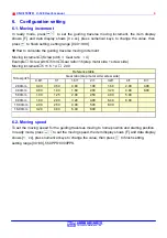
 How to calculate the guiding traverse moving increment 

Moving incremen

t

(Screw pitch 

×

 Gear ratio 

÷

 4) 

Example

 Screw pitch

5mm

Gear ratio=1.6(step motor side ÷ screw side) 

Moving incremen

t

5 ×1.6 ÷ 4 

 2.00 

Reference table 

Gear ratio (step motor side

0

screw side)


Screw pitch


0.8/1 1/1 1.6/1 2/1 3.2/1 4/1  8/1 

2.00mm 

0.40 

0.50 

0.80 

1.00 

1.60 

2.00 

4.00 

4.00mm 

0.80 

1.00 

1.60 

2.00 

3.20 

4.00 

8.00 

5.00mm

!

1.00 

1.25 

2.00 

2.50 

4.00 

5.00 


8.00mm 

1.60 

2.00 

3.20 

4.00 

6.40 

8.00 


10.00mm 

2.00 

2.50 

4.00 

5.00 

8.00 


16.00mm 

3.20 

4.00 

6.40 

8.00 


6.2. Moving speed 

To set the moving speed for the guiding traverses moving to home position and starting position. 

In ready mode, press

to set the moving speed, the item display shows [F], and data display 

shows [1    xx], press numerical keys to change the value, then press

  to finish setting, 

setting range [00~99], 550PPS~3000PPS. 


Summary of Contents for CNC-110STD

Page 1: ...s manual DOC NO 050523 1 TAILY AUTOMATION CO LTD 1 INTRODUCTION 2 2 FEATURES 2 3 FRONT PANEL 2 4 SPREADING PARAMETER SETTING 3 5 SPREADING OPERATION 3 6 CONFIGURATION SETTING 4 7 INSTALLATION AND WIR...

Page 2: ...able yarn and coil 2 Features Microprocessor design easy for program setting handling Non battery design using EEPROM for saving memory and can retain it for 10 years Build in step motor drive circuit...

Page 3: ...automatically get into ready mode in this mode when spindle is rotating the counting sensor will send the spreading signal to the controller and the guiding traverse will according to the setting val...

Page 4: ...ew side Moving increment 5 1 6 4 2 00 Reference table Gear ratio step motor side0screw side Screw pitch 0 8 1 1 1 1 6 1 2 1 3 2 1 4 1 8 1 2 00mm 0 40 0 50 0 80 1 00 1 60 2 00 4 00 4 00mm 0 80 1 00 1 6...

Page 5: ...s below otherwise it will count improperly Min Max Counting disc 1 0 Winding spindle 3 0 Zeroing sensor Zeroing disc Counting sensor The CNC 110STD do not need to use the Zeroing disc 7 2 Home sensor...

Page 6: ...3 CN1 BK GN W AC AC Earth 1 2 3 4 CN2 BK GN W A B A 1 2 3 4 5 CN3 R OR W 24V PHB PHA R B 0V HOME GN Y 24AWG 9C 100cm 0 5mm 4C 200cm 0 5mm 3C 180cm Y BL OR 1 2 3 4 5 1 5 CN4 1 3 RESET COM 0V 1 2 3 4 5...

Page 7: ...ons 90 0 10 0 8 0 8 0 174 0 59 0 72 5 131 5 CNC 110STD 3 2 x 2 51 0 14 5 15 0 14 5 3 5 12 0 9 0 13 0 7 0 10 0 6 0 1 5 51 0 22 0 22 0 3 5 3 2 x 2 7 0 10 0 6 0 1 5 5 0 10 0 R 2 8 0 R 1 3 0 R10 0 3 1 x 4...

Reviews: