background image

Contents


Installation & User Guide ...........................................................................................................VI


Chapter 1 Introduction ................................................................................................................ 1


1.1 Summary ........................................................................................................................................................... 1


1.2 System equipment ............................................................................................................................................ 2


1.3 Web control ....................................................................................................................................................... 3


1.4 Functions and features ..................................................................................................................................... 4


Chapter 2 Conference main unit................................................................................................. 5


2.1 Economical digital conference system main unit .............................................................................................. 6


2.1.1 Functions and instructions ........................................................................................................................................... 6


2.1.2 Installation and connection .......................................................................................................................................... 8


2.1.3 Configuration and operation ........................................................................................................................................ 9


2.2 USB Audio ...................................................................................................................................................... 18


2.2.1 Installation of USB Audio ........................................................................................................................................... 18


2.2.2 Digital audio input ...................................................................................................................................................... 19


2.2.3 Digital audio output .................................................................................................................................................... 20


2.3 Extension unit ................................................................................................................................................. 21


2.3.1 Functions and instructions ......................................................................................................................................... 21


2.3.2 Installation ................................................................................................................................................................. 22


Chapter 3 Conference units...................................................................................................... 23


3.1 Overview ......................................................................................................................................................... 23


3.2 Functions and instructions .............................................................................................................................. 24


3.3 Connection ...................................................................................................................................................... 25


3.3.1 Connecting to the CMU ............................................................................................................................................. 25


3.3.2 Connection between conference units ...................................................................................................................... 25


3.3.3 Connection between conference units ...................................................................................................................... 25


3.4 Operation ........................................................................................................................................................ 26


3.4.1 Delegate unit ............................................................................................................................................................. 26


3.4.2 Chairman unit ............................................................................................................................................................ 28


Chapter 4 System connection .................................................................................................. 29


4.1 Summary ......................................................................................................................................................... 29


4.1.1 Connection principles ................................................................................................................................................ 29


4.1.2 Connection cables ..................................................................................................................................................... 29


4.1.3 Extension cable ......................................................................................................................................................... 29


4.2 Connection between the CMU and the contribution units .............................................................................. 30


4.3 Connection between CMU and automatic video tracking system .................................................................. 31


4.4 Connection between CMU and network central control system ..................................................................... 32


Chapter 5 Web control ............................................................................................................. 33


5.1 Login and exit .................................................................................................................................................. 33


  IV 


Summary of Contents for EP-820AS

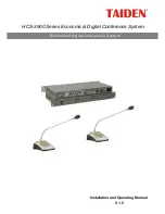
Page 1: ...HCS 3900 Series Economical Digital Conference System Installation and Operating Manual V 1 5 Economical Digital Conference System...

Page 2: ...es of the European directive 2014 30 EU To protect your hearing avoid high pressure level on earphones Adjust to a lower and convenient level If any detailed information is needed please contact your...

Page 3: ...apparatus has been damaged in any way such as power supply cord or plug is damaged liquid has been spilled or objects have fallen into the apparatus the apparatus has been exposed to rain or moisture...

Page 4: ...have power supplied to the unit whenever the power cord is inserted into the power source however the unit is operational only when the ON OFF switch is in the ON position The power cord is the main p...

Page 5: ...instructions 21 2 3 2 Installation 22 Chapter 3 Conference units 23 3 1 Overview 23 3 2 Functions and instructions 24 3 3 Connection 25 3 3 1 Connecting to the CMU 25 3 3 2 Connection between conferen...

Page 6: ...er 7 Working environment and maintenance 42 7 1 Public areas 42 7 2 Technical rooms 42 7 3 Ventilation 42 7 4 Cleaning 42 7 5 Storage 42 Chapter 8 Technical specifications 43 8 1 System specifications...

Page 7: ...ension unit of HCS 3900 20 Economical Digital Conference System Chapter 3 Conference unit Descriptions in detail of the functions and indications installation and connection configuration and operatio...

Page 8: ...sockets USB interface for digital audio input output HCS 3900ME Economical Digital Conference System Extension Unit Discussion units HCS 3938C Economical Digital Conference System Chairman Unit HCS 39...

Page 9: ...Economical Digital Conference System This system consists of one or more of the following items Conference Main Units HCS 3900MA 20 Economical Digital Conference System Main Unit discussion recording...

Page 10: ...irect and agile for use and move The professional 6P DIN standard plug and clasp improve system connection reliability while facilitate system installation and disassembly the daisy chain design of co...

Page 11: ...can access the IP address of main unit from web browser to manage centrally all aspects of the conference The operation turns out to be easy and efficient By Web page control functions of HCS 3900 co...

Page 12: ...ing and request list can be displayed on Web page and through which the operator can turn on off the microphones Speech time limit Predefined position setting video matrix setting and video switch 4 C...

Page 13: ...he Web control The devices that can be controlled by the CMU include discussion units and video switcher etc By conference extension units the Economical Digital Conference System can connect up to 25...

Page 14: ...2 1 Economical digital conference system main unit 2 1 1 Functions and instructions Figure 2 1 Conference main unit Front panel for HCS 3900MA 20 Front panel for HCS 3900MB 20 Backside Button 6...

Page 15: ...SD card slot Supports up to 32 G SD card for MP3 recording 12 Monitoring earphone interface 3 5 mm 13 Up button The OLED displays the UUUUUUUinitialUUUUUUU user interface press this button to select...

Page 16: ...able with a standard male connector When connecting the main unit to the contribution units just connect the 6P DIN male connector of the first unit to the output of the main unit For a longer distanc...

Page 17: ...ting the CMU should be configured through the dialog menu and the buttons The term interface used hereinafter means the information displayed on the OLED as the user interface The menu structure is sh...

Page 18: ...ce If the participant speaks into the microphone closely the microphone will be switched on automatically and off after a speech pause out of predefined time voice sensitivity level can be set up APPL...

Page 19: ...ter 2 Press the button to adjust volume 3 Press the MENU button to save and press the EXIT button to return to upper level menu 4 Audio Mode Audio Mode includes three submenus Normal Mode Remote Mode...

Page 20: ...Figure 2 5 Audio mode setting Normal Mode Figure 2 6 Audio mode setting Remote Mode Figure 2 7 Audio mode setting Insert Mode 12...

Page 21: ...to cancel 3 Press the EXIT button to return to upper level menu The maximal number of VIP units is 32 6 Speech Timer Set a speech time range 1 240 minutes 1 Press to set speech timer On Off If Off is...

Page 22: ...button all active microphones will mute temporarily when chairman releases Priority button all temporarily muted microphones will resume 2 Press MENU button to save and return to upper level menu 11 V...

Page 23: ...will turn to chairman unit If no chairman unit is present it will turn to VIP unit c Press the MENU button to save and return to upper level menu 14 Unit s Numbering Number the conference units Enter...

Page 24: ...ing to the recording time for example a file by the name of 140611 095110 means it is recorded at 09 51 10 on 2014 06 11 3 Press the MENU button to playback 4 Press the MENU button to stop or continue...

Page 25: ...s the button to select an operation language and then press the MENU button to confirm 2 1 3 7 About CMU information includes firmware version corporation information and series number shown as in the...

Page 26: ...Installation of USB Audio Once the HCS 3900M 20 main unit connects to the computer the HCS 3900M USB Audio will be detected automatically If it is connected for the first time the USB device driver wi...

Page 27: ...crophone HCS 3900M USB Audio and modify its setting on the Recording dialog box Shown as in the following figure Figurer2 10 Adjusting microphone volume Note Too high volume may lead to distortion so...

Page 28: ...dify its setting in the Playback dialog box as shown in the following figure Figurer2 11 Adjusting playback volume Note Please select the HCS 3900M USB Audio as the current device on playback Usually...

Page 29: ...ension input Connecting to CMU or last HCS 3900ME 4 Extension input indicator 5 Extension output with switch Connecting to next HCS 3900ME 6 Extension output indicator 7 Contribution unit outlet 6P DI...

Page 30: ...on The extension unit can be fixed on flat surface table wall ground etc Make holes on flat surface according to the following figure then fixed HCS 3900ME with M3 screws Figure 2 14 Installation of t...

Page 31: ...e term includes chairman unit VIP unit and delegate unit Product type HCS 3938C Economical Digital Conference System Chairman Unit HCS 3938D Economical Digital Conference System Delegate Unit HCS 3938...

Page 32: ...delegates requests to speak If the chairman microphone is not active pressing this key will activate it 2 Microphone On Off key for the chairman unit Microphone request key for the delegate unit Chair...

Page 33: ...connected to the CMU 3 3 2 Connection between conference units HCS 3938 series conference units of the HCS 3900 Economical Digital Conference System are daisy chained easily When connecting to anothe...

Page 34: ...o speak b Press this key again to cancel the request to speak c When an active microphone is turned off the first request microphone will be activated B Override mode Active microphone number limitati...

Page 35: ...ntrol knob on the main unit or by menu operation on the CMU front panel or by the Web page When the earphone is plugged its volume can be adjusted by the earphone volume control on the lateral side of...

Page 36: ...e as for the delegate unit refer to section 3 4 1 If the active microphone capacity is full the chairman cannot activate his her microphone But he she can use the Priority key to Mute All Microphones...

Page 37: ...ic control functions when through Web page to access the HCS 3900MA MB more powerful and versatile management and control functions are accessible 4 1 2 Connection cables HCS 3938 series conference un...

Page 38: ...and effortless Connect the first unit to the outlet connector of the CMU and following connect the plug of the cable of the second unit to the socket of the first unit Proceed one by one in a series...

Page 39: ...and focus on the speaker The view of the speaker will be displayed on large screen or other display devices The automatic video tracking system is compatible with several kinds of video signals and o...

Page 40: ...s electric devices such as DVD VCR TV projector etc RS 232C or RS 485 interfaces are available Remote controlling even from distant places can be achieved through LAN or internet TAIDEN HCS 6100 netwo...

Page 41: ...is admin and default Password is 123456 the password can be changed after login The default username is administrators that can not be deleted The login interface is shown in the following figure Fig...

Page 42: ...rix and Predefine Position etc 5 2 1 Assign Unit ID to Delegate It will list all ID of connective units in the system User can assign them to delegates open microphones set up the camera predefine pos...

Page 43: ...Off All Mic turn off all the microphones on the speaking list and request list Turn Off turn off the selected microphone Camera Ctrl click this button and set up the camera predefine position on the...

Page 44: ...te microphone turned on first Voice voice control mode the microphone On Off is controlled by voice participator speaks towards the microphone and turns it on In case of a speech pause the microphone...

Page 45: ...Figure 5 6 Video Matrix Select Video Input include Dome Camera Fixed Camera PC and Other Video Input Output Type include Normal and Video Track Save and send to CMU TMX 0804 matrix setup 1 Assign vide...

Page 46: ...trix switch 1 According to the setup of video matrix the video input type will be displayed automatically 2 Assign corresponding output channel by clicking on the cross point of input and output 3 Sel...

Page 47: ...d to CMU button to send the current predefined position to CMU if the adjustment is done 6 Repeat the above steps to set the predefined position for other seats microphones 7 Click the Save button on...

Page 48: ...st list Green flash or on Not first in request list Green on Note The according to the setup of Mic LED Setting menu on the front panel of CMU 3 Metal stem with goose neck to adjust angle and directio...

Page 49: ...0BH Interpreter headset stereo HCS 5100PA Headphone Other compatible types please refer to chapter eight 6 3 Accessories The dedicated accessories CBL6PS 6PIN dedicated extension cable is involved in...

Page 50: ...he operator in the control room and normal system operation Do not place objects on the top of units They could fall into vents or could cover them and thus prevent proper cooling of electronic compon...

Page 51: ...s Working conditions fixed stationary transportable Temperature range Transport 40 C to 70 C Operating 0 C to 45 C Max relative humidity 95 not condensing Safety Compliant with EN 60065 EMC emission C...

Page 52: ...ncy response 40 16000 Hz SNR 90 dBA Dynamic range 94 dB Total harmonic distortion 0 05 Mains power supply 100 240 V AC 50 60 Hz Audio input LINE IN 1 18 dBu balanced LINE IN 2 18 dBu unbalanced Audio...

Page 53: ...Installation Tabletop Dimensions mm Color Black Weight 1 5kg 8 2 2 2 Electrical characteristics Types HCS 3900ME Mains power supply AC 100 V 240 V 50 Hz 60 Hz Output load 1 k Maximum power consumption...

Page 54: ...aracteristics Conference unit HCS 3938 series Output frequency response 40 16000 Hz Earphone load 16 Earphone volume 10 mW Earphone output 3 5 mm stereo jack Max power consumption 2 W Connection 6P DI...

Page 55: ...30 mm 410 mm 470 mm Color Gray Silver Weight 85 g 95 g 105 g 8 3 2 2 Electrical characteristics Pluggable stem microphone MS33 41 47EME1G S Microphone type Uni directional electret condenser microphon...

Page 56: ...nce unit Hi Fi sound quality 150 Ohm 2 3 5 mm stereo jack Frequency response 20 Hz to 20 kHz Sensitivity 108 dBA 1 mW One sided wire Weight 90 g HCS 5100PA headphone Cooperates with the infrared recei...

Page 57: ...Appendix Dedicated 6 PIN Extension Cable 49...

Page 58: ...Copyright by TAIDEN Last Revision 12 2017 TAIDEN INDUSTRIAL CO LTD 6 F Block B Future Plaza 6060 Qiaoxiang Rd Nanshan District Shenzhen China P C 518053 Website http www taiden com...

Reviews: