Medio L400
46/51
Revision 1.8
June 2008
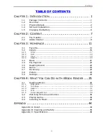
6.4 GPIO Connector
6.4.1 Pin Assignment
Figure 23: GPIO Connector (Female DB-9)
Table 12: GPIO Connector - Pin Assignment
Pin
Description
Pin
Description
1
Input #1
6
Output #1
2
Input #2
7
Output #2
3
Input #3
8
Output #3
4
Input #4
9
Output #4
5
Gnd
6.4.2 Electrical Characteristics
Table 13: GPIO Pins - Electrical Characteristics
Parameters
Min.
Max.
Unit
Maximum Input Voltage
28
V
Input Voltage (Low)
0
0.9
V
Input Voltage (High)
1.5
28
V
Maximum Output Current
2.8
A
Maximum Output Voltage
28
V
6.4.3 Using Inputs
Reader inputs can be driven by a voltage source from 0V up to 28V referring to the ground.
Voltages under 0.9V are considered as “logical low state”, voltages above 1.5V are considered as
“logical high state”. Inputs are internally pulled-up to 3.3V with 1KOhms resistors. Applying
negative voltage to inputs (polarity inversion) may destroy them.
Figure 24
below demonstrates how to connect an external sensor (a simple switch or a totem pole
output sensor) to an input.