


We know you are keen to get your 60i working. This section will
have you listening to your favourite music as quickly as possible.
If you fold out the front cover of this manual you will locate
diagrams which will help you find your way around your 60i
(1)
.
Make sure that all the components of your audio system are
disconnected from the AC supply whenever you change any
connections.
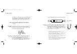
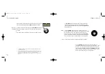
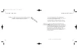
On the back of your 60i, you will find two pairs of loudspeaker
terminals, each pair consisting of one red and one black.
The terminals on the back of the 60i use BFA
(2)
sockets. The BFA
plug pushes into the middle of the terminal.
Use high-quality loudspeaker cable terminated in BFA plugs
(3)
to
connect the red
(4)
terminal of your right loudspeaker to the red
terminal marked
OUTPUT right
on the back of your 60i.
Then connect the black terminal of your right loudspeaker to the
black terminal marked
OUTPUT right
on the back of your 60i.
before
you start
loudspeaker
terminals
loudspeaker
connection
Connect the left loudspeaker to a pair of left terminals in the same way.
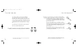
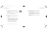
You will need a source of audio signals (such as our CD player
CD20R or our tuner T20) to feed into your 60i. Use a good-
quality, screened phono-phono audio cable to connect the phono
output sockets of your sound source to the appropriate pair of
left
and
right
sockets marked
SOURCE aux
,
tuner
,
cd
or
TAPE
in 1
,
in 2
or
in 3
on the back of your 60i
(6)
.
sound source
connection
10
11
getting started
getting started
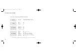
The diagram shows a
standard loudspeaker
arrangement
(5)
1. Throughout this instruction manual (except in titles),
bold
print indicates the
lettering that you will find on the panels of your 60i
2. In models for countries where the AC supply is 115 V, the terminals accept 4 mm
‘banana‘ plugs instead of BFA plugs. 4 mm plugs are not permitted in Europe.
Please see page 18 for more details of the terminals
3. If you prefer to use a cable which does not have BFA plugs, please see page 19
4. If your loudspeaker terminals are not colour coded – red corresponds to positive
(+) or signal and black corresponds to negative (-)
5. The diagram is for illustrative purposes only; it is not to scale and does not show
all connections. Please see page 18 for more details on connecting loudspeakers
6. The inputs for
cd
,
tuner
,
aux
,
TAPE 1
,
TAPE 2
and
TAPE 3
are all the same
electrically. They are named for your convenience
right speaker
lf
out
in
left speaker
GRA00046.1-[CA]60i 12/03/01 12:06 Page 11