background image

Hardware Installation Procedure

2-11

Eq

uip

m

ent Insta

lla

tio

2

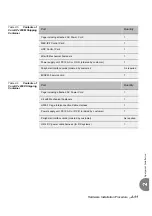
Table 2-5

Contents of 

Coral IPx 800M Shipping 
Container

Table 2-6

Contents of 

Coral IPx 800X Shipping 
Container

Part

Quantity

Cage including attached AC Power Cord

1

MEX-IP2 Control Card

1

HDC Control Card

1

Kit with Mechanical Fasteners

1

Power supply unit; PS19 AC or DC-D (ordered by customer)

1

Peripheral interface cards (ordered by customer)

As required

8DRC

M-2

 service card

1

Part

Quantity

Cage including attached AC Power Cord

1

Kit with Mechanical Fasteners

1

H500-1 Cage Interconnection Cable Harness

1

Power supply unit; PS19 AC or DC-D (ordered by customer)

1

Peripheral interface cards (ordered by customer)

As required

H614 DC power cable harness (for DC systems)

1

Summary of Contents for Coral IPx 800 Series

Page 1: ...Coral IPx 800 Installation Procedure and Hardware Reference Manual Document Edition 3 9 Creating a new world of IPportunities Eliezer Katzenstein Israel...

Page 2: ......

Page 3: ...tice or liability to make changes in equipment design or specifications Information supplied by the Manufacturer is believed to be accurate and reliable However no responsibility is assumed by the Man...

Page 4: ......

Page 5: ...porary discontinuance of service may be required If advance notice is not practical the telephone company will notify the customer as soon as possible Also you will be advised of your right to file a...

Page 6: ...representative designated by the supplier Any repairs or alterations made by the user to this equipment or equipment malfunctions may give the telecommunications company cause to request the user to d...

Page 7: ...markets through a single mark TUV on their product s which denotes compliance to U S and Canadian National Standards CB SCHEME Compliance Statement Equipment certified according to the CB SCHEME has b...

Page 8: ...ions limits of FCC Rules the following precautions must be observed while installing and operating the equipment 1 Install the equipment in strict accordance with the manufacturer s instructions 2 Ver...

Page 9: ...ectronic Equipment WEEE and with any applicable law and regulation promulgated in its respective Member State in connection with such Directive Accordingly the Distributor is responsible for and shall...

Page 10: ...vi...

Page 11: ...Requirements 2 3 Electrical Requirements 2 5 2 2 Equipment Installation Introduction 2 9 Mounting and Installing the Cage 2 10 Ground Wiring 2 17 Wiring DC Powered Systems 2 22 Wiring AC Powered Syst...

Page 12: ...ly Check 3 25 3 4 Installation Wrap up 3 27 Chapter 4 Software Installation Procedure 4 1 Generic Feature Software 4 1 Introduction 4 1 Upgrading Using FMprog PC Utility 4 2 4 2 MEX IP2 Status Display...

Page 13: ...5 45 PRI 23 PRI 30 Card Layout UDT C and later 5 48 T1 30T x 30T E Card Layout UDT C and later 5 49 UGW Card layout B1 and UGW E 5 50 PUGW Card 5 54 5 8 I O Connections Via Champ Connectors 5 57 Gene...

Page 14: ...ansion Cages 6 60 Suggestions for Peripheral Card Distribution 6 68 Optional Coral IPx 500X Expansion Cage 6 70 Chapter 7 Power Supplies 7 1 PS19 DC 7 1 General Description 7 1 Circuit Description 7 6...

Page 15: ...neral Information 8 7 When a DBM Card is Required 8 8 8 4 DBX 8 9 General Information 8 9 When a DBX Card is Required 8 10 8 5 IMC8 16 Integrated Flash Memory Cards 8 11 General Information 8 11 When...

Page 16: ......

Page 17: ...k 2 24 Figure 2 14 Coral IPx 800 Cage Rear Panel 2 25 Figure 2 15 Coral IPx 800 Power Connection for AC Systems 2 26 Figure 2 16 Coral IPx 800 Card Slot Position to I O Cable Pair Relationship 2 28 Fi...

Page 18: ...r PIN Assignment 5 29 Figure 5 14 PRI 23 PRI 30 layout UDT RJ 45 Interface Connector PIN Assignment 5 30 Figure 5 15 PRI 23 PRI 30 layout UDT DA 15S Interface Connector PIN Assignment 5 31 Figure 5 16...

Page 19: ...sed 6 4 Figure 6 2 Coral IPx 800 Cage with Door Opened 6 4 Figure 6 3 Coral IPx 800 System with Three Cages 6 5 Figure 6 4 Front Left Right and Top Views of Coral IPx 800 Cage 6 7 Figure 6 5 Left and...

Page 20: ...Cage 6 33 Figure 6 35 Left View of Coral IPx 800 Cage Mounted at Top of Rack 6 34 Figure 6 36 Labels on Rear Panel 6 36 Figure 6 37 Labels Inside Cage and Door 6 36 Figure 6 38 Coral IPx 800M Card Cag...

Page 21: ...Cages IPx 800M and two 500X 6 67 Figure 6 59 Coral IPx 800 PCM Highway Distribution 6 69 Figure 7 1 PS19 DC Front Panel Layout 7 3 Figure 7 2 PS19 DC Card Layout 7 5 Figure 7 3 PS19 DC Block Diagram...

Page 22: ......

Page 23: ...ng Surge Arrestor Device Specifications 5 12 Telephone Circuit Secondary Protection Device Specifications 5 13 Coral FlexSet APA APDL RS 232E Interface Pin Functions 5 22 DKT2000 with APA APDL RS 232E...

Page 24: ...16 PF G ES cards 5 67 I O Connections 4T C 4T CID 4T 4TMR 4TPF 4TMR PF S 12 16 PF G ES cards 5 68 I O Connections 8T C 8T CID 8T 8TPF 8T S 8T S PF S PF G ES cards 5 69 I O Connections 8T C 8T CID 8T 8...

Page 25: ...2 8SM cards 5 103 8SM cards 5 104 8DRCM 2 8DRCF 8DRCM cards 5 105 8DRCM 2 8DRCF 8DRCM cards 5 106 RMI ASU cards 5 107 RMI ASU cards 5 108 SKW x cards Issue 4 and later 5 109 SKW x cards Issue 4 and la...

Page 26: ...xix Coral IPx 800 System Configuration Options 6 53 Number of Universal I O Slots per System Configuration 6 54 Coral IPx 800 System Expansion Options 6 60 Time Slot Distribution in Coral IPx 800 6 68...

Page 27: ...Coral Cor IPx 800 Installation Manual Chapter 1 Introduction 1 1 Document Description 1 1 1 2 Special Symbols Used in this Document 1 5 1 3 System Description 1 7 1 3 Recommended Tools 1 9...

Page 28: ......

Page 29: ...complete new Coral IPx 800 and 3000 system installation Peripheral devices can be installed at any time after system installation For peripheral device installation refer to The Coral Terminal Equipm...

Page 30: ...Binary Backup PC Utility Coral Software Installation and Upgrade FMprog PC Utility Reference Manual Coral FlexAir Wireless Descriptions and Installation Procedure Coral FlexAir Wireless Systems Insta...

Page 31: ...e Troubleshooting and Hardware Reference T207M T208M T207M NP and T208M BL IP station Installation Manual T207S T208S T207S NP and T208S BL IP station Installation Manual FlexSet IP 280S IP station In...

Page 32: ...1 4 Coral IPx 800 Installation Manual Document Description 1 NOTES...

Page 33: ...g examples Indicates important information demanding special attention Points out a special procedure or a definition that is relevant but not central to the text Tip Advice that makes it easier to fo...

Page 34: ...1 6 Coral IPx 800 Installation Manual Special Symbols Used in this Document 1 NOTES...

Page 35: ...and time slot interchange functions for the PCM highways and the HDLC channels The peripheral circuitry is further divided into Shared Service and Peripheral Interface functions The shared service ci...

Page 36: ...natural development of the Coral IPx 3000 configurations The Coral IPx 4000 meets the demands of critical applications through its redundant common control system and fail safe backup operations inclu...

Page 37: ...for any Coral installation site Required Tools 3 16 1 4 and 5 16 straight blade screwdriver 1 and 2 Phillips screwdriver Diagonal wire cutters Long nosed pliers Electrician s pliers Slip joint pliers...

Page 38: ...ry generator Tone detector amplifier probe Telephone line test set with MF tone signaling capability Alligator clip leads AMPTM CHAMPTM installation tool Soldering iron and high quality rosin core sol...

Page 39: ...Coral Cor IPx 800 Installation Manual Chapter 2 Hardware Installation Procedure 2 1 Site Inspection 2 1 2 2 Equipment Installation 2 9 2 3 Program Interface Device Connection 2 47...

Page 40: ......

Page 41: ...ling of the installation area is finished or treated to prevent particle discharge 4 Verify that the installation area is well lit and that the light source is uniformly diffused without shadows Adequ...

Page 42: ...tric motors refrigeration units power transformers electric load centers and main circuit breaker panels 8 Verify that the installation area provides reasonable security to the system Room constructio...

Page 43: ...the rack according to system configuration see page 6 53 System Configuration Options function and the length of the cables interconnecting the cages Observe any order previously directed by a system...

Page 44: ...ear for a minimum of 3 feet 1 m due to the variety of cable termination hardware at the MDF 4 Verify that there is sufficient space for any additional equipment related to the Coral system such as Pro...

Page 45: ...itional branch circuit 2 A 1 85mm2 or 10AWG wire must be used in the circuit branch for 115VAC or 230VAC power 3 Each branch circuit must be independently protected by a fuse or a circuit breaker and...

Page 46: ...ully populated systems The total number may be defined per actual system The current is identical for main and expansion cages 115VAC 230VAC 48VDC IPx 800M 6A 3A 12A IPx 800X 6A 3A 12A IPx 500X 6A 3A...

Page 47: ...ily accessible listed branch circuit overcurrent protective device rated 30A 60VDC minimum slow blow must be incorporated in the building wiring for every four cages 4 CAUTION This equipment is design...

Page 48: ...2 8 Coral IPx 800 Installation Manual Site Inspection 2 NOTES...

Page 49: ...Powered Systems on page 2 25 Connecting the I O Cables on page 2 27 Setting the Configuration Jumpers on page 2 30 Interconnecting the Main and Expansion Cages on page 2 32 Installing the Power Supply...

Page 50: ...ossible to the installation area before opening 3 Using a utility knife carefully cut the tape securing the top flaps of the shipping carton and open the flaps 4 Remove any circuit card boxes in the d...

Page 51: ...rd 1 Kit with Mechanical Fasteners 1 Power supply unit PS19 AC or DC D ordered by customer 1 Peripheral interface cards ordered by customer As required 8DRCM 2 service card 1 Part Quantity Cage includ...

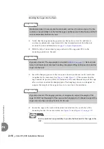
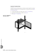
Page 52: ...ation see page 6 24 Removing the Door Removing the Locking Bar The locking bar for shipping reinforces the cage and prevents damage during shipping For more information see Figure 2 2 After it is deli...

Page 53: ...e hanging pin assembly on the bracket as depicted in step 2 of Figure 2 3 rotate the bracket 180 and align the bracket with the cage such that the narrow edge of the bracket is adjacent to the cage 4...

Page 54: ...upport the weight of the cage and are to be used only for assistance 4 Fasten the cage to the rack with fasteners inserted into the oval holes of the mounting bracket For more details see Figure 2 4 a...

Page 55: ...re 2 4 Left Side View of Coral IPx Cage Mounted onto 19 Rack Figure 2 5 Left Side View of Coral IPx Cage Mounted onto 23 Rack Hanging pin 19 Rack Nut not supplied by manufacturer Mounting bracket Hang...

Page 56: ...rrect In addition to customer requirements requirements for heat dissipation must be taken into account See page 6 30 Heat Buffer Bracket 1 If a heat buffer bracket is not necessary skip to page 2 17...

Page 57: ...an M4 threaded terminal pole that is fixed to the bottom right corner on the rear side of the cage by the manufacturer a serrated washer a flat washer and an M4 nut The cage ground wire is connected...

Page 58: ...over the serrated washer 3 Insert the flat washer onto the ground wire ring terminal 4 Fasten the hexagonal nut The hexagonal nut can be fastened or unfastened only with a closed 7mm hexagonal socket...

Page 59: ...d one flat washer Distance between screws 19 mm Figure 2 8 Master Ground Unit 2 Verify that the ground wire is 10AWG stranded conductor is the proper length and includes two ring terminals fitted onto...

Page 60: ...en Tighten until snug See Figure 2 8 6 Repeat step 1 through step 5 for all cages in the system Verify that the system ground wire connection between the different cages is identical to the schematic...

Page 61: ...on 2 Figure 2 10 Ground Connection for Coral IPx 800System with More than One Cage Including MDF Units 0 Master Ground R 1 0 ohm max Building Entrance Ground Main Cage 0 MDF Expansion Cage 1 10 AWG st...

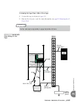
Page 62: ...be connected together in parallel with the H614 wire harness supplied There is no ground interconnection between different cages Therefore the GND terminal lugs are not in use Figure 2 11 DC Power Te...

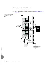
Page 63: ...cord For more information see page 6 20 Removing the AC Power Cord Figure 2 12 Coral IPx 800 Power Wiring for One Cage It is the customer s responsibility to supply the facilities DC fuse Master groun...

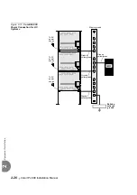
Page 64: ...ee page 6 20 Removing the AC Power Cord Figure 2 13 Coral IPx 800 Power Wiring for One Rack Fuse 48V RTN 48V RTN 48V 48V Fuse 48V RTN 48V RTN 48V 48V GND GND GND GND GND GND Fuse 48V RTN 48V RTN 48V 4...

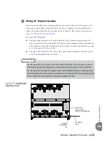
Page 65: ...signated power outlet For more information see page 6 21 Installing the AC Power Cord For cages that include an AC cord with a plug already attached route the power cord to the designated power outlet...

Page 66: ...Installation 2 Figure 2 15 Coral IPx 800 Power Connection for AC Systems Master ground Building entrance ground To AC power source To AC power source To AC power source Ground yellow green Ground yell...

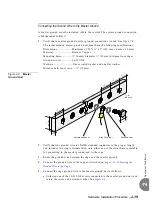
Page 67: ...into the Coral I O connector 4 Route the other end of the cable to the appropriate cable punch block on the MDF 5 Repeat this procedure for each I O cable moving from left to right across the upper I...

Page 68: ...s 17 42 24 49 Pair 25 50 25 34 26 9 1 25 50 50 NOT USED EVEN SLOTS 2 4 6 8 10 12 ODD SLOTS 1 3 5 7 9 11 ports 0 7 ports 0 7 ports 16 23 ports 16 23 ports 8 15 ports 8 15 Connector Pins LOWER CONNECTOR...

Page 69: ...30 cards are routed from the connectors of the front panel of Coral peripheral cards See page 5 25 I O Connections Via Front Panel 1 Determine the route of the RJ 45 cable from the network connection...

Page 70: ...1 Connect the static dissipating wrist strap connector to the cage and put on the strap See Figure 2 17 Figure 2 17 ESD Wrist Strap Connection on the Coral IPx 800 Cage 2 Remove all circuit cards from...

Page 71: ...pers in the IPx 800M Main Cage Table 2 9 Jumpers in the 800X Expansion Cage Jumpers Subject Refer to J29 Synchronization slots See Table 6 1 on page 6 39 Jumpers Subject Refer to J37 Synchronization s...

Page 72: ...e page 6 53 System Configuration Options 1 Verify that the power switches of all cages in the system are turned OFF 2 Route the cables from cage to cage according to the configurations defined on page...

Page 73: ...atic dissipating wrist strap connector to the cage and wear the strap 2 The power supply includes a ring generator that is required for single line telephone 8SLS 16SLS 24SLS cards or magneto telephon...

Page 74: ...de ridges located on the right panel of the power supply top and bottom with the card edge guides corresponding to the POWER SUPPLY marking at the bottom of the card cage and gently slide the power su...

Page 75: ...o 72440952900 INPUT CURRENT RATING 6A 115VAC 60Hz 3A 230VAC 50Hz 100 240VAC 47 63Hz PS19 AC OUTPUT 5VDC 13 0A 12VDC 3 0A 12VDC 0 15A 48VDC 7 0A 85VRMS 20 25Hz 12VA 120VDC 0 4A 5VDC 0 15A Alarm Red Ind...

Page 76: ...9 DC D power supply unit 2 In all cages that house a PS19 DC D power supply unit verify that the cage rear panel fuse is a 30A 125V S B otherwise replace the 15A 125V S B fuse by a 30A 125V S B fuse 3...

Page 77: ...gn the edges of the circuit card with the card edge guides in the card cage and gently slide the card straight into the card slot 5 A slight resistance will be felt as the multi pin connectors on the...

Page 78: ...d into the card slot on the extreme right slot of the main cage The cage is normally shipped with this card inserted in its card slot Partially extract it from its card slot such that the cards protru...

Page 79: ...service card into slot 1 of the expansion cage In a system with two expansion cages insert a PX card into slot 1 of the first expansion cage and insert a shared service card into slot 1 of the second...

Page 80: ...ish card placement prior to installation Refer to the Coral IPx 500 Installation Manual Chapter 2 and the Coral Service and Peripheral Cards Installation Manual Place digital trunk interface cards in...

Page 81: ...interface characteristics or operation Peripheral Digital Trunk Interface PRI 23 PRI 30 T1 30T 30TE 30TM 30T x 2DT UDT 4 8TBR 8TBRP DPC SS7 Peripheral Station Interface 8 16 24SFT 8SM 8 24SA 8 16 24S...

Page 82: ...d MEX IP2 with optional DBM DBX or MAP CLA Peripheral service card HDC 1 2 3 4 5 6 7 8 9 Card Type Card Type Card Type Card Type Card Type Card Type Card Type Card Type Universal I O Universal I O Uni...

Page 83: ...ype Card Type Card Type Card Type Card Type Card Type Universal I O Universal I O Universal I O Universal I O Universal I O Universal I O Universal I O Universal I O Card Type Card Type Universal I O...

Page 84: ...Card Type Card Type Card Type Card Type Card Type Card Type Universal I O Universal I O Universal I O Universal I O Universal I O Universal I O Universal I O Universal I O Card Type Card Type Univers...

Page 85: ...Peripheral Card Placement Diagram 1 6 2 7 3 8 4 9 5 10 Card Type Card Type Card Type Card Type Card Type Card Type Card Type Card Type Card Type Card Type Power Supply PS500 AC DC PS Type Yes No Cora...

Page 86: ...e Peripheral Card Placement Diagram 1 6 2 7 3 8 4 9 5 10 Card Type Card Type Card Type Card Type Card Type Card Type Card Type Card Type Card Type Card Type Power Supply PS500 AC DC PS Type Yes No Cor...

Page 87: ...he default settings for all serial programming ports of the Coral system 2 Obtain or prepare a serial data cable to connect the PI device to the KB0 serial programming port on the front panel of the M...

Page 88: ...4 DATA TERMINAL READY 25 14 1 1 2 RECEIVE DATA 3 TRANSMIT DATA 5 SIGNAL GROUND DATA SET READY 6 CLEAR TO SEND 5 REQUEST TO SEND 4 RECEIVE DATA 3 TRANSMIT DATA 2 SIGNAL GROUND 7 PC Async Serial Port or...

Page 89: ...oral Cor IPx 800 Installation Manual Chapter 3 Initial Powerup Tests 3 1 Power Supply Test 3 1 3 2 Common Control Test 3 9 3 3 Shared Service and Peripheral Card Test 3 19 3 4 Installation Wrap up 3 2...

Page 90: ......

Page 91: ...ered system or as a DC powered system For PS19 DC powered systems skip to page 3 2 For PS19 DC D powered systems skip to page 3 4 For PS19 AC powered systems skip to page 3 6 1 General Before proceedi...

Page 92: ...r Terminal Interconnection page 2 23 Coral IPx 800 Power Wiring for One Cage page 2 24 Coral IPx 800 Power Wiring for One Rack Measure the voltage as follows Connect the positive lead of the DMM to th...

Page 93: ...r indicator is lit while the red Alarm indicator is not lit If the red alarm indicator illuminates see page 7 13 Troubleshooting PS19 DC 10 Turn OFF downwards the power switch on the front panel of th...

Page 94: ...he DMM to the 48V RTN IN terminal Connect the negative lead to the 48V IN terminal Verify that the reading is 48 volt DC 5 Verify that the PS19 DC D power switch is turned OFF downwards 3 PS19 DC D Po...

Page 95: ...thus securing the card to the cage as well as grounding the unit 8 Turn the PS19 DC D power switch ON and verify that the green Power indicator is lit while the red Alarm indicator is not lit If the r...

Page 96: ...IPx 800 Power Connection for AC Systems 5 Insert the male plug of the AC power cord into the AC line outlet or primary power receptacle designated for the system 4 AC Powered System Connecting the PO...

Page 97: ...at the top and bottom of the unit front panel thus securing the card to the cage as well as grounding the unit 9 Turn the PS19 AC power switch ON and verify that the green Power indicator is lit whil...

Page 98: ...Power Supply Test 3 Figure 3 1 Internal View of the Coral IPx 800 Cage Configuration jumpers AC power supply connector PS19 AC Multi pin connectors for cards Door release mechanism Grounding wire for...

Page 99: ...o MEX IP2 interface connectors P1 P2 or P3 See Figure 3 2 for the location of the memory interface connectors See Figure 3 4 and Figure 3 5 for the MAP CLA and DBM DBX cards If installed remove the MA...

Page 100: ...right 12 Attach the Program Interface PI device cable to the KB0 programming port connector on the front side of the MEX IP2 card Verify that the PI device is configured to match the data rate word le...

Page 101: ...CHECKING MEX CONTROLS CHECKING SAU END CHECKING SAU Patch Loaded CHECKING CODING MEMORY CODING MEMORY IS O K END CHECKING CODING MEMORY CHECKING MEX CONTROLS END CHECKING MEX CONTROLS CHECKING SAU END...

Page 102: ...age 8 5 for details b Carefully remove the plastic insulation from under the top contact of the lithium battery holder on the MEX IP2 card refer to Figure 3 2 22 If a MAP CLA card is supplied with the...

Page 103: ...short messages as described in Step 17 that appear during system start up CCS is on the air ROOT CCS xx xx xx Copyright c 2001 yyyy NAME site name SAU The second message indicates that the system has...

Page 104: ...emory Interface Connector Locations BATTERY INSULATOR PULL AS SHOWN TO REMOVE IMC8 16 Card Software Database Flash memory card REMOVE BEFORE USE Database Memory Backup Battery LIU Rear LIU Front DBM M...

Page 105: ...Reset CPU Pushbutton Expansion Panel For CLA or MAP Application cards LAN Indicator Green RJ 45 Network Interface Connection Option DIP Switches 2 8 Always Set to the Right 1 Set to the Left for LAN...

Page 106: ...ON 4 Status indicator LED Reset pushbutton Maintenance RS 232 port RJ 45 LAN port P2 P6 J2 U25 Hard disk connector 1 2 3 4 ON OFF Reset pushbutton Status indicator LED JU1 MAP CLA DIP switch selector...

Page 107: ...ry Insulator pull As Shown To Remove CLA DBX RST LED COM 1 LINE 100Base T CoraLINK FCLA CFCLA Module RJ 45 Network Interface Ethernet 10 100Base T LED Maintenance RS 232 Port Reset Pushbutton Status I...

Page 108: ...not lost save the database to the IMC8 IMC16 flash memory card via the database controls branch of the system database PI Route ROOT 0 10 2 2 0 See Chapter 4 3 of the Control Card Installation Manual...

Page 109: ...ontrol card they will not initialize properly The card installation is described on page 3 20 Rules for Inserting a Coral Circuit Card The Coral IPx 800 system peripheral cards installation and initia...

Page 110: ...s The LED remains illuminated continuously until the card receives its database from the system After a few seconds verify that the LED extinguishes An extinguished diagnostic LED indicates that the c...

Page 111: ...helf 1 3 5 7 9 11 13 15 the even expansion cage is labeled shelf 2 4 6 10 12 14 Slot Number Identifies the slot location of the indicated card for display In the main cage the range of slot numbers is...

Page 112: ...t SIZES to support unsupported sub circuits for 8DRCM 2 8DRCF card Partial Active for the iDSP card is not critical Readjust the parameter value only when needed REPLACED P_TYPE and I_TYPE are not com...

Page 113: ...age 2 42 Coral IPx 800M Main Cage Peripheral Card Placement Diagram page 2 43 Coral IPx 800X 1st Exp Cage Peripheral Card Placement Diagram page 2 44 Coral IPx 800X 2nd Exp Cage Peripheral Card Placem...

Page 114: ...so that the installation corresponds with the uniform numbering plan 4 On the front panel of the PS19 unit verify that the green power indicator is lit while the red alarm indicator is not lit Second...

Page 115: ...ry two cages insert at least one peripheral card into the cage that does NOT include the PS19 DC D card Verify that the shared service card or peripheral card initializes If the system includes a PS19...

Page 116: ...3 26 Coral IPx 800 Installation Manual Shared Service and Peripheral Card Test 3 NOTES...

Page 117: ...the cage front door See page 6 23 Closing the Door 3 Close the MDF cover 4 Repeat step 1to step 3 for all system cages 5 Remove any other items from the shipping containers 6 Remove all empty package...

Page 118: ...3 28 Coral IPx 800 Installation Manual Installation Wrap up 3 NOTES...

Page 119: ...Coral Cor IPx 800 Installation Manual Chapter 4 Software Installation Procedure 4 1 Generic Feature Software 4 1 4 2 MEX IP2 Status Display Codes 4 3...

Page 120: ......

Page 121: ...A application adapter for loading a new Coral software version Whenever an updated version of the IPx 800 software is released the upgrade is delivered to the sites either on a disk e mail or via othe...

Page 122: ...copied i e the Coral generic software version the switch authorization and the database The manufacturer highly recommends to keep a copy of the current files located at each customer site Copies sho...

Page 123: ...ower is lost Each time a programming session is started from the PI any faulty battery is identified The system database should be saved as soon as possible to an IMC8 IMC16 unit and the faulty batter...

Page 124: ...ode 8 Appears briefly during powerup before other numbers 1 2 3 4 5 6 Appear Briefly During Initialization b Lithium Backup Battery MEX IP2 or DBX Low C Flash Memory IMC8 Checksum Error E Map RAM Codi...

Page 125: ...tion Frame 5 1 5 2 External Equipment 5 5 5 3 Protection Devices 5 11 5 4 Power Fail PF Transfer Circuits 5 17 5 5 Terminal Data Communication Ports 5 21 5 6 I O Connections Via Front Panel 5 25 5 7 I...

Page 126: ......

Page 127: ...lding and energy management systems Therefore care should be taken to plan the MDF layout before fastening components to the wall or mounting surface such as Trunk circuits Wired and wireless station...

Page 128: ...ar Panel on page 5 25 Tip It is recommended to terminate all the I O connectors available in the system on punch blocks at the MDF even if some cables are not initially used This saves time and effort...

Page 129: ...Figure 5 1 MDF Connections 48V 48VRTN I O cables from upper connectors I O cables from lower connectors to CO RJ45 to Ethernet network Connections from the rear panel of a Coral IPx cage Routing hole...

Page 130: ...d together in the same loop will reduce the maximum possible loop length of the station or trunk Always match the twisted pair of a loop to corresponding tip and ring connections Do not connect the wi...

Page 131: ...jack configurations with wire designations for four station types 2 wire SLT single line telephones and digital station sets FlexSet APDL CPA GKT DKT DST 2 wire DIM and VDM need only connect Tip T and...

Page 132: ...onal external power via line connector pins 2 and 5 see Coral Terminal Equipment Installation Manual 2 2SK 4SK 8SK discontinued no longer available EKT VIC Vision Impaired Console KSI EIS ACC ACC R SD...

Page 133: ...UpB R Pin 3 Red AR DRT UpB R Blu Wht AR DRT UpB R Blu Wht AR DRT R UpB Pin 4 Green AT DTT T UpA Pin 4 Green AT DTT UpA T Wht Blu AT DTT T UpA Wht Blu AT DTT T UpA Pin 4 Green AT DTT T UpA Pin 5 Yellow...

Page 134: ...section consult the following documentation Station Type Manual CoralAIR wireless handset SKW RBS CoralAIR Wireless Systems Installation Manual FlexAir wireless handset SKK RBS FlexAir Wireless System...

Page 135: ...building Determine if the telecommunication connection protective devices meet the specifications described in the following section Protection Devices on page 5 11 If not install secondary protector...

Page 136: ...locks Individual auxiliary interface circuits can then be cross connected from Coral IPx 800 I O punch blocks to other punch blocks that terminate music circuits relay wiring and other external equipm...

Page 137: ...le 5 2 lists minimum specifications Secondary surge and impulse protectors that further limit voltages on a telephone circuit to prevent damage to electronic equipment Table 5 3 lists minimum specific...

Page 138: ...kage current protector in series of every wire tip and ring on every port that is either connected to the public telephone network or to an out of the building cable The requirement is in accordance w...

Page 139: ...easurement Surge Impulse Protector Clamp Points DC 2kV S 100V S 10kV S 230VDC Max 230VDC Max 100VDC Max 30VDC Max Response Time 5nS Max Series Resistance 15 Max Sneak Current Protector Acceptance UL L...

Page 140: ...1 Identify the MDF disconnecting strips used for telephone connections 2 Place a Magazine 10 Surge Arrestor CN 7244 3190009 on each MDF strip used for telephone See Step 1 in Figure 5 6 3 Use the rel...

Page 141: ...estor to MDF Step 1 Mount a Magazine 10 Surge Arrestor on each MDF disconnection strip used for telephone circuit cross connections CN 7244 3190009 Use a Surge Voltage Protector for cross connected te...

Page 142: ...5 16 Coral IPx 800 Installation Manual Protection Devices 5 NOTES...

Page 143: ...e wiring interconnections between the trunk card station card and an SLT and EKT PF station set respectively Coral FlexSet GKT DKT and DST cannot be used as power failure stations Trunks The following...

Page 144: ...entered in the system database Refer to Power Fail Trunk Definition in Chapter 8 Program Interface Reference Manual for more information Power Failure Trunk Definition Route TRK 4 FROM TO DIAL Enter t...

Page 145: ...ng To Single Line 500 2500 Telephone Set Lightning Protection Trunk Circuit With PF Option Coral IPx 800 3000 4000 Red R ring Green T tip Modular Jack Ground Start Button 2500 Single Line Set STy SRy...

Page 146: ...nued no longer available CORAL SYSTEM Trunk Circuit with PF Option 2SK 4SK 8SK TTx TRx SCTx SCRx ATy ARy STTx STRx 1 2 3 4 5 6 7 8 9 0 OPER ABC DEF GHI JKL PRS TUV WXY VOL VOL DTy DRy YELLOW DR BLACK...

Page 147: ...rate of up to 19 2Kbps The interface appears at a DB 25S connector on the rear panel of the APDL and DKT2000 with an APA RJ 45 jack connector on the rear panel of the FlexSet 80 GKT FlexSet APDL FlexS...

Page 148: ...232E Interface Pin Functions 9 6 8 7 6 5 4 3 2 1 9 8 7 6 5 4 3 2 1 Data Terminal Ready DTR Transmit Data TR Receive Data RD Data Carrier Detector DCD NC Clear To Send CTS Request To Send RTS Data Set...

Page 149: ...or DCD NC Clear To Send CTS Request To Send RTS Data Set Ready DSR Signal Ground GND To PC Serial Port COM 1 2 To GKT RS 232 9 pin female connector 1 GKT RS 232 8 8 1 RJ 45 socket female external view...

Page 150: ...5 24 Coral IPx 800 Installation Manual Terminal Data Communication Ports RS 232E 5 NOTES...

Page 151: ...ardware Reference Manual 8SKK and 16SKK cards include front panel I O options However there are various factors involved Therefore their description is not included in this section For details see the...

Page 152: ...e following cards may be connected via the cage rear panel with an RJ 45 connector for each card slot 2 Connections on the Cage Rear Panel 2DT Card PRI 23 PRI 30 T1 30T or 30TM Configuration on page 5...

Page 153: ...Installation Manual 2DT RJ 45 Network Connector Pinout Table 5 6 2DT Network Interface Connections Figure 5 11 2DT RJ 45 Interface Connector PIN Assignment 3 2DT Card PRI 23 PRI 30 T1 30T or 30TM Conf...

Page 154: ...rear panel interface 0 Verify that interface 0 is not connected from the front and rear panels simultaneously Table 5 15 and Figure 5 32 on page 5 47 describe the possible network interface connectio...

Page 155: ...ace Connections Figure 5 13 PRI 23 PRI 30 layout A B DA 15S Interface Connector PIN Assignment 4 PRI 23 PRI 30 Card PRI Layout A B page 5 29 PRI Layout UDT page 5 30 DA 15S Pin Nomination Function Pin...

Page 156: ...5 17 describes the connection from the front panel to the PSTN LTU CSU Table 5 8 PRI 23 PRI 30 layout UDT Network Interface Connections Figure 5 14 PRI 23 PRI 30 layout UDT RJ 45 Interface Connector P...

Page 157: ...Tx B Rx B Rx A Tx A GND Shield 48 VDC 3 8 1 15 13 11 9 DA 15S D TYPE Connector Slide Latch Down to Lock Up to Release 1 9 8 15 15 14 13 12 11 10 9 8 7 6 5 4 3 2 1 8 7 6 5 4 3 2 1 SHIELD Rx B Ring Rx...

Page 158: ...cators Network Interface Connectors Maintenance Port PRI 23 L O S R A I C R C G E N DA 9S D Type DA 15S D Type RJ 45 Pin Pin 11 RxB Pin 3 RxA Pin 8 Shield Pin 9 TxB Pin 1 TxA Pin 2 4 5 6 7 10 12 14 No...

Page 159: ...allation Manual T1 30T x 30T Layout A B discontinued Table 5 9 T1 30T layout A B Network Interface Connections Figure 5 18 T1 30T layout A B RJ 45 Interface Connector PIN Assignment 5 T1 30T x 30T E C...

Page 160: ...describes the connection from the front panel to the PSTN LTU CSU Table 5 10 T1 30T layout UDT Network Interface Connections Figure 5 19 T1 30T layout UDT RJ 45 Interface Connector PIN Assignment Do n...

Page 161: ...Ring Rx Tip Tx Tip GND Shield 48 VDC 3 8 1 15 13 11 9 DA 15S D TYPE Connector Slide Latch Down to Lock Up to Release 1 9 8 15 15 14 13 12 11 10 9 8 7 6 5 4 3 2 1 8 7 6 5 4 3 2 1 SHIELD Rx B Ring Rx A...

Page 162: ...ing Pin 1 Tx Tip Pin 2 4 5 6 7 10 12 14 Not Used Pin 13 48VDC Pin 15 Ground Nomination Pin Pin 1 Rx Ring Pin 2 Rx Tip Pin 3 Shield Pin 4 Tx Ring Pin 5 Tx Tip Pin 6 Shield Pin 7 48VDC Pin 8 Ground Nomi...

Page 163: ...pe connector for DPC card Figure 5 23 DPC TO CO TO CORAL Connector Pin Assignments 6 DPC Card Discontinued Pin No Nomination Function Pin 1 Tx Tip Send Data Pin 9 Tx Ring Send Data Pin 3 Rx Tip Receiv...

Page 164: ...s shown in Figure 5 24 to facilitate RJ 45 connection from the front panel as required in the Coral IPx 4000 system Therefore if the RJ 45 connection is to be made in the from the cage rear panel repo...

Page 165: ...W Network Interface Connections Figure 5 25 UGW Network Interface Connector PIN Assignment For further information on how to make the connection refer also to the Coral Voice Over IP Installation Manu...

Page 166: ...o the LAN WAN Pin Pin 1 Tx Pin 2 Tx Pin 3 Rx Pin 4 not used Pin 5 not used Pin 6 Rx Pin 7 not used Pin 8 not used Nomination SPEED Yellow lit when running at 100Mbps LINK ACTIVE Green lit when cable c...

Page 167: ...ections Figure 5 27 IPG Network Interface Connector PIN Assignment For further information see the VoIP Gateway IPG Card Installation Manual 8 IPG Card Pin Nomination Connection Pin 1 Tx Transmit Data...

Page 168: ...tion to the LAN WAN LAN WAN Pin Pin 1 Tx Pin 2 Tx Pin 3 Rx Pin 4 not used Pin 5 not used Pin 6 Rx Pin 7 not used Pin 8 not used Nomination Rcv Data packets are being transmitted green System LED red L...

Page 169: ...volved Therefore their description is not included in this section For details see the Coral VoIP Installation Procedure and Hardware Reference Manual There are two types of Coral IPx 800 systems back...

Page 170: ...5 44 Coral IPx 800 Installation Manual I O RJ 45 Connections Via Rear Panel For Coral Interface Cards 5 Figure 5 29 Coral IPx 800 Back Panel and RJ 45 Rear Connectors RJ 45 Connectors...

Page 171: ...2DT RJ 45 Network Connector Pinout Table 5 14 2DT Network Interface Connections Figure 5 30 2DT RJ 45 Front and Rear Panel Interface Connector PIN Assignment 2 2DT Card PRI 23 PRI 30 T1 30T or 30TM Co...

Page 172: ...B Pin 2 RxA Pin 3 Shield GND Pin 4 TxB Pin 5 TxA Nomination RJ 45 2DT L O S R A I C R C G E N 0 1 0 1 Card status Indicator Trunk alarm status Maintenance port RS 232 serial 9 pin male RJ 45 network i...

Page 173: ...cted from the front and rear panels simultaneously Table 5 15 and Figure 5 32 describe the possible network interface connections from the card front panel and the cage rear panel Table 5 15 2DT Possi...

Page 174: ...tor Table 5 16 and Figure 5 33 Figure 5 33 describes the connection from the rear panel to the PSTN LTU CSU Table 5 16 PRI 23 PRI 30 layout UDT C Rear Panel RJ 45 Network Interface Connections Figure...

Page 175: ...5 17 and Figure 5 34 Figure 5 34 describes the connection from the rear panel to the PSTN LTU CSU Table 5 17 T1 30T layout UDT C Rear Panel RJ 45 Network Interface Connections Figure 5 34 T1 30T layo...

Page 176: ...5 38 The UGW and UGW E cards communicate via the RJ 45 connection on the cage rear panel for Coral IPx 800 3000 card front panel for Coral IPx 4000 The ULI 1 daughterboard is attached to the UGW and...

Page 177: ...Panel For Coral Interface Cards 5 Figure 5 35 UGW Card MG Media Gateway module ULI 1 location for Coral IPx 800 3000 MAC address MG ULI 1 shipped location for Coral IPx 4000 MAC 00208F0718FE MAC addre...

Page 178: ...E cards The interface connections are the same for the front and rear panels MG Media Gateway module DC to DC power supply Present ONLY in UGW E ULI 1 location for Coral IPx 800 3000 MAC address MG UL...

Page 179: ...or further information on how to make the connection refer also to the Coral Voice Over IP Installation Manual Pin Nomination Function Pin 1 Tx Transmit Data to Network Pin 2 Tx Transmit Data to Netwo...

Page 180: ...ear panel RJ 45 connector for the PUGW card The interface connections are the same for the front and rear panels Table 5 19 PUGW Rear Panel RJ 45 Network Interface Connections Figure 5 38 PUGW Rear Pa...

Page 181: ...Cards 5 Figure 5 39 PUGW Card PUGW MAINT LNK SPD ETHERNET 10 100 MG MAC 000A6B004DF9 MAC 000A6B004DFA MAC 000A6B004DFB IXP 0 A maintenance port Not used MAC addresses coded during manufacturing proces...

Page 182: ...5 56 Coral IPx 800 Installation Manual I O RJ 45 Connections Via Rear Panel For Coral Interface Cards 5 NOTES...

Page 183: ...ear panel connections are shown in Section 5 7 I O RJ 45 Connections Via Rear Panel on page 5 43 Table Presentation Each I O connector services two universal I O slots There are two I O connection tab...

Page 184: ...ctor relationship tables The possible connections for each cards are highlighted by the shaded areas The table is divided in two sections The upper section represent the connections for cards inserted...

Page 185: ...Wh Gn 3 Gn Wh 29 Wh Br 4 Br Wh 30 Wh Sl 5 Sl Wh 31 Rd Bl 6 Bl Rd 32 Rd Or 7 Or Rd 33 Rd Gn 8 Gn Rd 34 Rd Br 9 Br Rd 3rd Port Group 2nd Port Group 35 Rd Sl 10 Sl Rd 36 Bk Bl 11 Bl Bk 37 Bk Or 12 Or Bk...

Page 186: ...11 Bl Bk 29 Wh Br 4 Br Wh 37 Bk Or 12 Or Bk 30 Wh Sl 5 Sl Wh 38 Bk Gn 13 Gn Bk 31 Rd Bl 6 Bl Rd 39 Bk Br 14 Br Bk 32 Rd Or 7 Or Rd 40 Bk Sl 15 Sl Bk 33 Rd Gn 8 Gn Rd 41 Yw Bl 16 Bl Yw Odd Slots Pin C...

Page 187: ...hone 4S SH 4SH S LL cards 5 95 8SA 8SLS 8SH S LL 8S 8S SH cards 5 97 16SLS 16SH S LL 16S cards 5 99 8SM cards 5 103 24SA 16SLS 24SLS cards 5 101 Digital Trunks 4TBR 8TBR 4TBRP 8TBRP cards 5 65 2 Card...

Page 188: ...T CID cards 5 69 8TPF 8T S PF G ES cards 5 69 I O Connections 4ALS 4ALS M cards 5 71 8ALS 8ALS M cards 5 73 8DID 8DID S 8DID S Z cards 5 75 8BID cards 5 77 4GID 4TWL cards 5 79 Auxiliary Cards 8DRCM 2...

Page 189: ...K cards 5 83 24SDT cards 5 93 24SLS cards 5 101 I O Connections 4ALS 4ALS M cards 5 71 4GID 4TWL cards 5 79 4S SH 4SH S LL 5 95 4SK 8SK cards 5 85 4T C 4T CID cards 5 67 4T 4TPF S 12 16 G ES cards 5 6...

Page 190: ...C 8T CID cards 5 69 8T 8TPF 8T S 8T S PF cards 5 69 8T S G 8T S PF G cards 5 69 8TBR 8TBRP cards 5 65 8DRCM 2 8DRCF 8DRCM cards 5 105 The 4 8 16 SH S SH SH S SH S LL cards with message waiting are not...

Page 191: ...R 1 R 5 R 5 30 Wh Sl 5 Sl Wh T 2 T 2 T 6 T 6 31 Rd Bl 6 Bl Rd R 2 R 2 R 6 R 6 32 Rd Or 7 Or Rd T 3 T 3 T 7 T 7 33 Rd Gn 8 Gn Rd R 3 R 3 R 7 R 7 34 Rd Br 9 Br Rd T 4 T 4 35 Rd Sl 10 Sl Rd R 4 R 4 36 B...

Page 192: ...Or Bk 30 Wh Sl 5 Sl Wh T 2 T 2 T 6 T 6 38 Bk Gn 13 Gn Bk 31 Rd Bl 6 Bl Rd R 2 R 2 R 6 R 6 39 Bk Br 14 Br Bk 32 Rd Or 7 Or Rd T 3 T 3 T 7 T 7 40 Bk Sl 15 Sl Bk 33 Rd Gn 8 Gn Rd R 3 R 3 R 7 R 7 41 Yw B...

Page 193: ...ower Connector 26 Wh Bl 1 Bl Wh TT2 TR2 27 Wh Or 2 Or Wh STT2 STR2 28 Wh Gn 3 Gn Wh TT0 TR0 SCT2 SCR2 29 Wh Br 4 Br Wh STT0 STR0 TT3 TR3 30 Wh Sl 5 Sl Wh SCT0 SCR0 STT3 STR3 31 Rd Bl 6 Bl Rd TT1 TR1 S...

Page 194: ...5 Rd Sl 10 Sl Rd 28 Wh Gn 3 Gn Wh TT0 TR0 SCT2 SCR2 36 Bk Bl 11 Bl Bk 29 Wh Br 4 Br Wh STT0 STR0 TT3 TR3 37 Bk Or 12 Or Bk 30 Wh Sl 5 Sl Wh SCT0 SCR0 STT3 STR3 38 Bk Gn 13 Gn Bk 31 Rd Bl 6 Bl Rd TT1 T...

Page 195: ...TR0 TT4 TR4 27 Wh Or 2 Or Wh TT1 TR1 STT4 STR4 28 Wh Gn 3 Gn Wh TT2 TR2 SCT4 SCR4 29 Wh Br 4 Br Wh STT2 STR2 TT5 TR5 30 Wh Sl 5 Sl Wh SCT2 SCR2 STT5 STR5 31 Rd Bl 6 Bl Rd TT3 TR3 SCT5 SCR5 32 Rd Or 7...

Page 196: ...Wh Gn 3 Gn Wh TT2 TR2 SCT4 SCR4 36 Bk Bl 11 Bl Bk 29 Wh Br 4 Br Wh STT2 STR2 TT5 TR5 37 Bk Or 12 Or Bk 30 Wh Sl 5 Sl Wh SCT2 SCR2 STT5 STR5 38 Bk Gn 13 Gn Bk 31 Rd Bl 6 Bl Rd TT3 TR3 SCT5 SCR5 39 Bk...

Page 197: ...Wh TT2 TR2 27 Wh Or 2 Or Wh STT2 STR2 28 Wh Gn 3 Gn Wh TT0 TR0 SCT2 SCR2 29 Wh Br 4 Br Wh STT0 STR0 TT3 TR3 30 Wh Sl 5 Sl Wh SCT0 SCR0 STT3 STR3 31 Rd Bl 6 Bl Rd TT1 TR1 SCT3 SCR3 32 Rd Or 7 Or Rd STT...

Page 198: ...8 Wh Gn 3 Gn Wh TT0 TR0 SCT2 SCR2 36 Bk Bl 11 Bl Bk 29 Wh Br 4 Br Wh STT0 STR0 TT3 TR3 37 Bk Or 12 Or Bk 30 Wh Sl 5 Sl Wh SCT0 SCR0 STT3 STR3 38 Bk Gn 13 Gn Bk 31 Rd Bl 6 Bl Rd TT1 TR1 SCT3 SCR3 39 Bk...

Page 199: ...TR1 STT4 STR4 28 Wh Gn 3 Gn Wh TT2 TR2 SCT4 SCR4 29 Wh Br 4 Br Wh STT2 STR2 TT5 TR5 30 Wh Sl 5 Sl Wh SCT2 SCR2 STT5 STR5 31 Rd Bl 6 Bl Rd TT3 TR3 SCT5 SCR5 32 Rd Or 7 Or Rd STT3 STR3 TT6 TR6 33 Rd Gn...

Page 200: ...6 Bk Bl 11 Bl Bk 29 Wh Br 4 Br Wh STT2 STR2 TT5 TR5 37 Bk Or 12 Or Bk 30 Wh Sl 5 Sl Wh SCT2 SCR2 STT5 STR5 38 Bk Gn 13 Gn Bk 31 Rd Bl 6 Bl Rd TT3 TR3 SCT5 SCR5 39 Bk Br 14 Br Bk 32 Rd Or 7 Or Rd STT3...

Page 201: ...TT6 TR6 29 Wh Br 4 Br Wh TT3 TR3 TT7 TR7 30 Wh Sl 5 Sl Wh 31 Rd Bl 6 Bl Rd 32 Rd Or 7 Or Rd 33 Rd Gn 8 Gn Rd 34 Rd Br 9 Br Rd TT4 TR4 35 Rd Sl 10 Sl Rd TT5 TR5 36 Bk Bl 11 Bl Bk TT6 TR6 37 Bk Or 12 O...

Page 202: ...3 TT7 TR7 37 Bk Or 12 Or Bk 30 Wh Sl 5 Sl Wh 38 Bk Gn 13 Gn Bk 31 Rd Bl 6 Bl Rd 39 Bk Br 14 Br Bk 32 Rd Or 7 Or Rd 40 Bk Sl 15 Sl Bk 33 Rd Gn 8 Gn Rd 41 Yw Bl 16 Bl Yw Odd Slots Pin Color Upper Connec...

Page 203: ...h TT5 TR5 30 Wh Sl 5 Sl Wh 31 Rd Bl 6 Bl Rd TT3 TR3 32 Rd Or 7 Or Rd TT6 TR6 33 Rd Gn 8 Gn Rd TT7 TR7 34 Rd Br 9 Br Rd TT4 TR4 35 Rd Sl 10 Sl Rd 36 Bk Bl 11 Bl Bk 37 Bk Or 12 Or Bk TT5 TR5 38 Bk Gn 13...

Page 204: ...h Sl 5 Sl Wh 38 Bk Gn 13 Gn Bk 31 Rd Bl 6 Bl Rd TT3 TR3 39 Bk Br 14 Br Bk 32 Rd Or 7 Or Rd TT6 TR6 40 Bk Sl 15 Sl Bk 33 Rd Gn 8 Gn Rd TT7 TR7 41 Yw Bl 16 Bl Yw Odd Slots Pin Color Upper Connector Lowe...

Page 205: ...R0 29 Wh Br 4 Br Wh TT3 TR3 30 Wh Sl 5 Sl Wh 31 Rd Bl 6 Bl Rd TT1 TR1 32 Rd Or 7 Or Rd 33 Rd Gn 8 Gn Rd 34 Rd Br 9 Br Rd TT2 TR2 35 Rd Sl 10 Sl Rd 36 Bk Bl 11 Bl Bk 37 Bk Or 12 Or Bk TT3 TR3 38 Bk Gn...

Page 206: ...Or 12 Or Bk 30 Wh Sl 5 Sl Wh 38 Bk Gn 13 Gn Bk 31 Rd Bl 6 Bl Rd TT1 TR1 39 Bk Br 14 Br Bk 32 Rd Or 7 Or Rd 40 Bk Sl 15 Sl Bk 33 Rd Gn 8 Gn Rd 41 Yw Bl 16 Bl Yw Odd Slots Pin Color Upper Connector Lowe...

Page 207: ...0 SB0 M2 SB2 30 Wh Sl 5 Sl Wh ETT1 ETR1 ETT3 ETR3 31 Rd Bl 6 Bl Rd ERT1 ERR1 ERT3 ERR3 32 Rd Or 7 Or Rd E1 SG1 E3 SG3 33 Rd Gn 8 Gn Rd M1 SB1 M3 SB3 34 Rd Br 9 Br Rd ETT2 ETR2 35 Rd Sl 10 Sl Rd ERT2 E...

Page 208: ...0 Wh Sl 5 Sl Wh ETT1 ETR1 ETT3 ETR3 38 Bk Gn 13 Gn Bk 31 Rd Bl 6 Bl Rd ERT1 ERR1 ERT3 ERR3 39 Bk Br 14 Br Bk 32 Rd Or 7 Or Rd E1 SG1 E3 SG3 40 Bk Sl 15 Sl Bk 33 Rd Gn 8 Gn Rd M1 SB1 M3 SB3 41 Yw Bl 16...

Page 209: ...1 Bl Wh 27 Wh Or 2 Or Wh 28 Wh Gn 3 Gn Wh 29 Wh Br 4 Br Wh 30 Wh Sl 5 Sl Wh AT0 AR0 31 Rd Bl 6 Bl Rd DT0 DR0 32 Rd Or 7 Or Rd AT1 AR1 33 Rd Gn 8 Gn Rd DT1 DR1 34 Rd Br 9 Br Rd 35 Rd Sl 10 Sl Rd 36 Bk...

Page 210: ...l 11 Bl Bk 29 Wh Br 4 Br Wh 37 Bk Or 12 Or Bk 30 Wh Sl 5 Sl Wh AT0 AR0 38 Bk Gn 13 Gn Bk 31 Rd Bl 6 Bl Rd DT0 DR0 39 Bk Br 14 Br Bk 32 Rd Or 7 Or Rd AT1 AR1 40 Bk Sl 15 Sl Bk 33 Rd Gn 8 Gn Rd DT1 DR1...

Page 211: ...Wh Gn 3 Gn Wh AT1 AR1 AT5 AR5 29 Wh Br 4 Br Wh DT1 DR1 DT5 DR5 30 Wh Sl 5 Sl Wh AT2 AR2 AT6 AR6 31 Rd Bl 6 Bl Rd DT2 DR2 DT6 DR6 32 Rd Or 7 Or Rd AT3 AR3 AT7 AR7 33 Rd Gn 8 Gn Rd DT3 DR3 DT7 DR7 34 R...

Page 212: ...9 Wh Br 4 Br Wh DT1 DR1 DT5 DR5 37 Bk Or 12 Or Bk 30 Wh Sl 5 Sl Wh AT2 AR2 AT6 AR6 38 Bk Gn 13 Gn Bk 31 Rd Bl 6 Bl Rd DT2 DR2 DT6 DR6 39 Bk Br 14 Br Bk 32 Rd Or 7 Or Rd AT3 AR3 AT7 AR7 40 Bk Sl 15 Sl...

Page 213: ...DRT5 29 Wh Br 4 Br Wh DTR1 DRR1 DTR5 DRR5 30 Wh Sl 5 Sl Wh DTT2 DRT2 DTT6 DTR6 31 Rd Bl 6 Bl Rd DTR2 DRR2 DTR6 DRR6 32 Rd Or 7 Or Rd DTT3 DRT3 DTT7 DRT7 33 Rd Gn 8 Gn Rd DTR3 DRR3 DTR7 DRR7 34 Rd Br 9...

Page 214: ...DTR5 DRR5 37 Bk Or 12 Or Bk 30 Wh Sl 5 Sl Wh DTT2 DRT2 DTT6 DTR6 38 Bk Gn 13 Gn Bk 31 Rd Bl 6 Bl Rd DTR2 DRR2 DTR6 DRR6 39 Bk Br 14 Br Bk 32 Rd Or 7 Or Rd DTT3 DRT3 DTT7 DRT7 40 Bk Sl 15 Sl Bk 33 Rd G...

Page 215: ...B11 A11 30 Wh Sl 5 Sl Wh B4 A4 B12 A12 31 Rd Bl 6 Bl Rd B5 A5 B13 A13 32 Rd Or 7 Or Rd B6 A6 B14 A14 33 Rd Gn 8 Gn Rd B7 A7 B15 A15 34 Rd Br 9 Br Rd B8 A8 35 Rd Sl 10 Sl Rd B9 A9 36 Bk Bl 11 Bl Bk B10...

Page 216: ...A11 37 Bk Or 12 Or Bk 30 Wh Sl 5 Sl Wh B4 A4 B12 A12 38 Bk Gn 13 Gn Bk 31 Rd Bl 6 Bl Rd B5 A5 B13 A13 39 Bk Br 14 Br Bk 32 Rd Or 7 Or Rd B6 A6 B14 A14 40 Bk Sl 15 Sl Bk 33 Rd Gn 8 Gn Rd B7 A7 B15 A15...

Page 217: ...Wh B3 A3 30 Wh Sl 5 Sl Wh B4 A4 31 Rd Bl 6 Bl Rd B5 A5 32 Rd Or 7 Or Rd B6 A6 33 Rd Gn 8 Gn Rd B7 A7 34 Rd Br 9 Br Rd 35 Rd Sl 10 Sl Rd 36 Bk Bl 11 Bl Bk 37 Bk Or 12 Or Bk 38 Bk Gn 13 Gn Bk 39 Bk Br...

Page 218: ...B3 A3 37 Bk Or 12 Or Bk 30 Wh Sl 5 Sl Wh B4 A4 38 Bk Gn 13 Gn Bk 31 Rd Bl 6 Bl Rd B5 A5 39 Bk Br 14 Br Bk 32 Rd Or 7 Or Rd B6 A6 40 Bk Sl 15 Sl Bk 33 Rd Gn 8 Gn Rd B7 A7 41 Yw Bl 16 Bl Yw Odd Slots P...

Page 219: ...Br Wh B3 A3 B11 A11 30 Wh Sl 5 Sl Wh B4 A4 B12 A12 31 Rd Bl 6 Bl Rd B5 A5 B13 A13 32 Rd Or 7 Or Rd B6 A6 B14 A14 33 Rd Gn 8 Gn Rd B7 A7 B15 A15 34 Rd Br 9 Br Rd B16 A16 B8 A8 35 Rd Sl 10 Sl Rd B17 A1...

Page 220: ...3 A3 B11 A11 37 Bk Or 12 Or Bk B19 A19 30 Wh Sl 5 Sl Wh B4 A4 B12 A12 38 Bk Gn 13 Gn Bk B20 A20 31 Rd Bl 6 Bl Rd B5 A5 B13 A13 39 Bk Br 14 Br Bk B21 A21 32 Rd Or 7 Or Rd B6 A6 B14 A14 40 Bk Sl 15 Sl B...

Page 221: ...SR3 30 Wh Sl 5 Sl Wh 31 Rd Bl 6 Bl Rd 32 Rd Or 7 Or Rd 33 Rd Gn 8 Gn Rd 34 Rd Br 9 Br Rd 35 Rd Sl 10 Sl Rd 36 Bk Bl 11 Bl Bk 37 Bk Or 12 Or Bk 38 Bk Gn 13 Gn Bk 39 Bk Br 14 Br Bk 40 Bk Sl 15 Sl Bk 41...

Page 222: ...5 Sl Wh 38 Bk Gn 13 Gn Bk 31 Rd Bl 6 Bl Rd 39 Bk Br 14 Br Bk 32 Rd Or 7 Or Rd 40 Bk Sl 15 Sl Bk 33 Rd Gn 8 Gn Rd 41 Yw Bl 16 Bl Yw Odd Slots Pin Color Upper Connector Lower Connector Pin Color Lower C...

Page 223: ...29 Wh Br 4 Br Wh ST3 SR3 ST7 SR7 30 Wh Sl 5 Sl Wh 31 Rd Bl 6 Bl Rd 32 Rd Or 7 Or Rd 33 Rd Gn 8 Gn Rd 34 Rd Br 9 Br Rd ST4 SR4 35 Rd Sl 10 Sl Rd ST5 SR5 36 Bk Bl 11 Bl Bk ST6 SR6 37 Bk Or 12 Or Bk ST7...

Page 224: ...7 37 Bk Or 12 Or Bk 30 Wh Sl 5 Sl Wh 38 Bk Gn 13 Gn Bk 31 Rd Bl 6 Bl Rd 39 Bk Br 14 Br Bk 32 Rd Or 7 Or Rd 40 Bk Sl 15 Sl Bk 33 Rd Gn 8 Gn Rd 41 Yw Bl 16 Bl Yw Odd Slots Pin Color Upper Connector Lowe...

Page 225: ...d Bl 6 Bl Rd ST5 SR5 ST13 SR13 32 Rd Or 7 Or Rd ST6 SR6 ST14 SR14 33 Rd Gn 8 Gn Rd ST7 SR7 ST15 SR15 34 Rd Br 9 Br Rd ST8 SR8 35 Rd Sl 10 Sl Rd ST9 SR9 36 Bk Bl 11 Bl Bk ST10 SR10 37 Bk Or 12 Or Bk ST...

Page 226: ...31 Rd Bl 6 Bl Rd ST5 SR5 ST13 SR13 39 Bk Br 14 Br Bk 32 Rd Or 7 Or Rd ST6 SR6 ST14 SR14 40 Bk Sl 15 Sl Bk 33 Rd Gn 8 Gn Rd ST7 SR7 ST15 SR15 41 Yw Bl 16 Bl Yw Odd Slots Pin Color Upper Connector Lowe...

Page 227: ...Or Rd ST6 SR6 ST14 SR14 33 Rd Gn 8 Gn Rd ST7 SR7 ST15 SR15 34 Rd Br 9 Br Rd ST16 SR16 ST8 SR8 35 Rd Sl 10 Sl Rd ST17 SR17 ST9 SR9 36 Bk Bl 11 Bl Bk ST18 SR18 ST10 SR10 37 Bk Or 12 Or Bk ST19 SR19 ST1...

Page 228: ...T20 SR20 31 Rd Bl 6 Bl Rd ST5 SR5 ST13 SR13 39 Bk Br 14 Br Bk ST21 SR21 32 Rd Or 7 Or Rd ST6 SR6 ST14 SR14 40 Bk Sl 15 Sl Bk ST22 SR22 33 Rd Gn 8 Gn Rd ST7 SR7 ST15 SR15 41 Yw Bl 16 Bl Yw ST23 SR23 Od...

Page 229: ...29 Wh Br 4 Br Wh ST3 SR3 ST7 SR7 30 Wh Sl 5 Sl Wh 31 Rd Bl 6 Bl Rd 32 Rd Or 7 Or Rd 33 Rd Gn 8 Gn Rd 34 Rd Br 9 Br Rd ST4 SR4 35 Rd Sl 10 Sl Rd ST5 SR5 36 Bk Bl 11 Bl Bk ST6 SR6 37 Bk Or 12 Or Bk ST7...

Page 230: ...7 37 Bk Or 12 Or Bk 30 Wh Sl 5 Sl Wh 38 Bk Gn 13 Gn Bk 31 Rd Bl 6 Bl Rd 39 Bk Br 14 Br Bk 32 Rd Or 7 Or Rd 40 Bk Sl 15 Sl Bk 33 Rd Gn 8 Gn Rd 41 Yw Bl 16 Bl Yw Odd Slots Pin Color Upper Connector Lowe...

Page 231: ...3 27 Wh Or 2 Or Wh RTS1 CTS1 RTS3 CTS3 28 Wh Gn 3 Gn Wh DTR1 DSR1 DTR3 DSR3 29 Wh Br 4 Br Wh TXD2 RXD2 RLY1 RLY1 30 Wh Sl 5 Sl Wh RTS2 CTS2 RLY2 RLY2 31 Rd Bl 6 Bl Rd DTR2 DSR2 RLY3 RLY3 32 Rd Or 7 Or...

Page 232: ...Sl Rd 28 Wh Gn 3 Gn Wh DTR1 DSR1 DTR3 DSR3 36 Bk Bl 11 Bl Bk 29 Wh Br 4 Br Wh TXD2 RXD2 RLY1 RLY1 37 Bk Or 12 Or Bk 30 Wh Sl 5 Sl Wh RTS2 CTS2 RLY2 RLY2 38 Bk Gn 13 Gn Bk 31 Rd Bl 6 Bl Rd DTR2 DSR2 R...

Page 233: ...S3 28 Wh Gn 3 Gn Wh DTR1 DSR1 DTR3 DSR3 29 Wh Br 4 Br Wh TXD2 RXD2 RLY1 RLY1 30 Wh Sl 5 Sl Wh RTS2 CTS2 RLY2 RLY2 31 Rd Bl 6 Bl Rd DTR2 DSR2 RLY3 RLY3 32 Rd Or 7 Or Rd M P1 M P1 33 Rd Gn 8 Gn Rd M P2...

Page 234: ...R3 DSR3 36 Bk Bl 11 Bl Bk 29 Wh Br 4 Br Wh TXD2 RXD2 RLY1 RLY1 37 Bk Or 12 Or Bk 30 Wh Sl 5 Sl Wh RTS2 CTS2 RLY2 RLY2 38 Bk Gn 13 Gn Bk 31 Rd Bl 6 Bl Rd DTR2 DSR2 RLY3 RLY3 39 Bk Br 14 Br Bk 32 Rd Or...

Page 235: ...3 Gn Wh TT BS2 TR BS2 29 Wh Br 4 Br Wh RT BS2 RR BS2 30 Wh Sl 5 Sl Wh CLK 2M CLK 2M 31 Rd Bl 6 Bl Rd CLK 8K CLK 8K 32 Rd Or 7 Or Rd PLS 320 ms PLS 320 ms 33 Rd Gn 8 Gn Rd RS 485 RS 485 34 Rd Br 9 Br R...

Page 236: ...Br Wh RT BS2 RR BS2 37 Bk Or 12 Or Bk 30 Wh Sl 5 Sl Wh CLK 2M CLK 2M 38 Bk Gn 13 Gn Bk 31 Rd Bl 6 Bl Rd CLK 8K CLK 8K 39 Bk Br 14 Br Bk 32 Rd Or 7 Or Rd PLS 320 ms PLS 320 ms 40 Bk Sl 15 Sl Bk 33 Rd...

Page 237: ...1 A1 28 Wh Gn 3 Gn Wh B2 A2 29 Wh Br 4 Br Wh B3 A3 30 Wh Sl 5 Sl Wh B4 A4 31 Rd Bl 6 Bl Rd B5 A5 32 Rd Or 7 Or Rd B6 A6 33 Rd Gn 8 Gn Rd B7 A7 34 Rd Br 9 Br Rd 35 Rd Sl 10 Sl Rd 36 Bk Bl 11 Bl Bk 37 B...

Page 238: ...h Br 4 Br Wh B3 A3 37 Bk Or 12 Or Bk 30 Wh Sl 5 Sl Wh B4 A4 38 Bk Gn 13 Gn Bk 31 Rd Bl 6 Bl Rd B5 A5 39 Bk Br 14 Br Bk 32 Rd Or 7 Or Rd B6 A6 40 Bk Sl 15 Sl Bk 33 Rd Gn 8 Gn Rd B7 A7 41 Yw Bl 16 Bl Yw...

Page 239: ...0 A10 29 Wh Br 4 Br Wh B3 A3 B11 A11 30 Wh Sl 5 Sl Wh B4 A4 B12 A12 31 Rd Bl 6 Bl Rd B5 A5 B13 A13 32 Rd Or 7 Or Rd B6 A6 B14 A14 33 Rd Gn 8 Gn Rd B7 A7 B15 A15 34 Rd Br 9 Br Rd B8 A8 35 Rd Sl 10 Sl R...

Page 240: ...A11 37 Bk Or 12 Or Bk 30 Wh Sl 5 Sl Wh B4 A4 B12 A12 38 Bk Gn 13 Gn Bk 31 Rd Bl 6 Bl Rd B5 A5 B13 A13 39 Bk Br 14 Br Bk 32 Rd Or 7 Or Rd B6 A6 B14 A14 40 Bk Sl 15 Sl Bk 33 Rd Gn 8 Gn Rd B7 A7 B15 A15...

Page 241: ...Px 800 Installation Manual Chapter 6 Cage Description 6 1 Cage Description and Installation 6 3 6 2 Coral IPx 800M Main Cage 6 39 6 3 Coral IPx 800X Expansion Cage 6 45 6 4 System Configuration Option...

Page 242: ......

Page 243: ...found in Chapter 2 0 The cage houses all hardware components of the Coral IPx 800 system including the power supply unit control cards peripheral cards and the I O connections The cages are designed...

Page 244: ...e and electromagnetic and radio frequency interference EMI and RFI They meet or exceed all specifications of telecommunications and electrical safety authorities world wide Peripheral interface connec...

Page 245: ...Description 6 5 Cage Description and Installation 6 Figure 6 3 displays the system configuration with three cages mounted onto a rack with the door closed Figure 6 3 Coral IPx 800 System with Three C...

Page 246: ...of the system The Coral IPx 800 cage includes slots for control service and peripheral cards a slot for the power supply unit door locking studs free space at the bottom of the cage designed for cool...

Page 247: ...bottom for incoming cool air and locking studs on the left side of the door Figure 6 4 Front Left Right and Top Views of Coral IPx 800 Cage Cage door Right mounting bracket Right cable routing hole L...

Page 248: ...with 19 racks If the cage is to be mounted on a 23 rack the bracket must be reassembled accordingly as described on page 2 13 Preparing the Cage for Mounting onto a 23 Rack Routing holes at the bottom...

Page 249: ...heat from the lower cage is released through the bottom rear side of the cage above When other systems are installed directly above the Coral cage a heat buffer bracket must be installed See page 6 2...

Page 250: ...is moved from the unlocked position to the locked position by inserting a screwdriver blade into the stud slot and turning counter clockwise half a turn Figure 6 7 Front View of Cage Door The inside...

Page 251: ...el Figure 6 10 Coral IPx 800X Rear Panel 3 Rear Panel 9 RJ 45 I O connectors AC power cord Ground terminal DC power cover Spare fuse Set of Velcro nylon straps for securing cables Four upper I O conne...

Page 252: ...Chapter 3 LAN RJ 45 Connectors The Coral IPx 800M cage includes two RJ 45 LAN connectors on the rear panel The left connector is used for LAN connection to LIU The right connector is for future use Ca...

Page 253: ...of I O Champ connectors upper and lower serve two peripheral cards even and odd Figure 6 11 illustrates the card slot to I O Champ connector relationship Pair 25 on each I O connector is not used Fig...

Page 254: ...Not used ODD SLOTS ODD SLOTS EVEN SLOTS Wht Blu Pairs 1 8 Pairs 9 16 Red Grn Red Brn Ylw Blu Ylw Org Vio Brn Pairs 17 24 Pair 25 Not used ODD SLOTS EVEN SLOTS EVEN SLOTS Wht Blu Pairs 1 8 Pairs 9 16 R...

Page 255: ...attached to the rear panel with two M4 screws on the top side of the cover See Figure 6 14 The bottom side of the cover includes two angles that form extrusions which are inserted into two mating slo...

Page 256: ...r in the counter clockwise direction 2 Lift and unhook the extrusion at the bottom of the DC cover from the rear panel Place the screws in a safe place for reassembly 3 Remove the DC power cover Figur...

Page 257: ...ion at the bottom of the DC cover into the two mating slots on the rear panel 2 Push the DC cover closed 3 Fasten the two M4 screws in the clockwise direction Figure 6 16 DC Cover Installation Push co...

Page 258: ...the power wiring of the cage DC Power Fuse The DC power fuse is attached to the rear panel of the cage underneath the DC power cover All cages include a fuse rated 30A 125V S B All cages are shipped...

Page 259: ...r details 3 Replace only with the same type and rating of fuse A spare fuse is located on the DC power cover 4 Close the DC power cover See page 6 17 Closing the DC Power Cover for details 5 Replace t...

Page 260: ...assemble the AC power cover over the space vacated by the AC connector 5 Close the DC power cover See page 6 17 Closing the DC Power Cover 6 Store the AC power cord and screws for future reassembly Fi...

Page 261: ...t to the AC power opening 4 Assemble the AC power cord with the two M3 screws 5 Close the DC power cover See page 6 17 Closing the DC Power Cover Figure 6 20 AC Power Cord Assembly Fasten the screws w...

Page 262: ...opens to 110 Figure 6 21 Opening the Door 6 Accessing the Cage Interior Electrical Hazard Contact with live internal components could cause shock burn or death During system operation the cage door mu...

Page 263: ...locking studs with a straight blade screwdriver half a turn clockwise Figure 6 22 Closing the Door Fire Hazard The free space at the bottom of the cage is designed to allow cool air to flow into the c...

Page 264: ...t a straight blade screwdriver between the door release mechanism and the right panel of the cage and pry the door release mechanism outwards while lifting the door upwards 4 At the same time lift and...

Page 265: ...e cage form an angle that is greater than 90 See Figure 6 24 2 Lower the door onto the hinges and push down until the door clicks into place 3 From the bottom of the cage connect the grounding wire pl...

Page 266: ...o common control cards eight peripheral cards and one service card The Coral IPx 800 includes one IPx 800M cage for all configurations See Figure 6 26 for a view of the IPx 800M backplane For more inf...

Page 267: ...l Cards The control cards are housed in the right side of the main cage These cards are described in detail in Chapter 8 The Coral IPx 800 includes the MEX IP2 and the HDC control cards Peripheral Car...

Page 268: ...e routed via the free space at the bottom of the cage through the hole either on the left or right side See Figure 6 28 Figure 6 28 Cable Routing from the Front of the Cage Power supply connector Conf...

Page 269: ...t must be reassembled accordingly as described on page 2 13 Preparing the Cage for Mounting onto a 23 Rack Figure 6 29 displays the cage mounted onto a 19 rack and Figure 6 30 displays the cage mounte...

Page 270: ...he cage and could result in a fire The bottom panel of the cage is angled such that it forms a gap between the bottom panel and the top panel of the cage underneath This gap allows the warm air to be...

Page 271: ...al heat buffer brackets independently Unless otherwise specified the cages are shipped with 19 brackets It is the customer s responsibility to order 23 brackets instead of 19 brackets if required Figu...

Page 272: ...cage 1 and through the bottom of cage 2 See Figure 6 33 For this reason whenever a Coral IPx 800 cage is mounted directly above another Coral IPx 800 cage there is no need to install a heat buffer bra...

Page 273: ...supplied cage cage 2 a free space of 1 U 1 75 or 45 mm must be maintained above the top panel of the Coral IPx 800 cage See Figure 6 34 To meet this requirement a heat bracket must be installed direc...

Page 274: ...Px 800 cage cage 2 is mounted at the top of the rack a heat buffer bracket must be installed on top of the cage to ensure that no equipment can be installed directly above the cage See Figure 6 35 Fig...

Page 275: ...ces For further information see PS19 DC DC Power Supply Specifications on page 7 16 PS19 DC D DC Power Supply Duplication Specifications on page 7 37 PS19 AC AC Power Supply Specifications on page 7 5...

Page 276: ...HE FCC RULES OPERATION IS SUBJECT TO THE FOLLOWING TWO CONDITIONS 1 THIS DEVICE MAY NOT CAUSE HARMFUL INTERFERENCE AND 2 THIS DEVICE MUST ACCEPT ANY INTERFERENCE RECEIVED INCLUDING INTERFERENCE THAT M...

Page 277: ...connect all I O cables from the front panel and remove them from the free space beneath the cage For more information see page 6 26 Cage Interior 7 For 19 cages remove the front door to obtain access...

Page 278: ...6 38 Coral IPx 800 Installation Manual Cage Description and Installation 6 NOTES...

Page 279: ...nit slot See Figure 6 38 The first two right slots are reserved for the common control cards MEX IP2 and HDC For further information see Chapter 8 The following eight universal I O slots numbered 1 8...

Page 280: ...DC D Main processor card MEX IP2 with optional DBM DBX or MAP CLA Peripheral service card HDC Universal I O slot Universal I O slot Universal I O slot Universal I O slot Universal I O slot Universal...

Page 281: ...connectors one service card connector and the configuration jumpers The backplane is displayed in Figure 6 39 Figure 6 39 Coral IPx 800M Backplane 0 0 0 2 Backplane Description SPARE PRM SYNC SEC SYN...

Page 282: ...d in each of the IPx 800X 500X expansion cages Card slot 4 in all cages is wired to operate as the primary external clock synchronization source marked PRM SYNC Card slot 5 in all cages is wired as th...

Page 283: ...n Slot 5 Slot 4 Primary N A Secondary N A N A Secondary N A Primary 4 5 SEC SYNC I O slot PRM SYNC I O slot 4 5 SEC SYNC I O slot PRM SYNC I O slot Shelf 2 Shelf 1 PRM SYNC I O slot 4 5 SEC SYNC I O s...

Page 284: ...D type 25 pin female connector that can be used to connect two cages that house a PS19 DC D power supply unit in one or both of the cages The connection is made with an H719 cable supplied with the p...

Page 285: ...st of components supplied with the IPx 800X cage see Table 2 6 on page 2 11 0 The expansion cage contains twelve card slots that are numbered 1 through 12 from right to left See Figure 6 42 Slot 1 is...

Page 286: ...Card Cage Front View Power supply PS19 AC DC 1 2 3 4 5 6 7 8 9 10 11 12 Service Card or PX card slot Universal I O slot Universal I O slot Universal I O slot Universal I O slot Universal I O slot Univ...

Page 287: ...ice or PX card connector the power supply connector the AC power input and the configuration jumpers The backplane is displayed in Figure 6 43 Figure 6 43 Coral IPx 800X Backplane 2 Backplane Descript...

Page 288: ...in slot 4 J37 bottom 2 pins Connected Secondary synchronization card in slot 5 Not connected Secondary synchronization card not in slot 5 J38 Z6 top pin Z6 bottom pin Z5 top pin Z5 bottom pin Not con...

Page 289: ...igure 6 44 displays the jumper configuration for each cage designation The shelves in a Coral IPx Office system however are designated 1 2 and 3 for the main unit first and second expansion cages resp...

Page 290: ...external clock synchronization source marked PRM SYNC Card slot 5 in all cages is wired as the secondary external clock synchronization source marked SEC SYNC The expansion cage can house the primary...

Page 291: ...expansion cage The connection is made with an H500 1 cable that is supplied with the expansion cage P1 is a D type 25 pin female connector that can be used to connect two cages that house a PS19 DC D...

Page 292: ...6 52 Coral IPx 800 Installation Manual Coral IPx 800X Expansion Cage Description 6 NOTES...

Page 293: ...age 6 45 Coral IPx 800X Expansion Cage The Coral IPx 800 can operate as a system in any one of the following configurations Table 6 5 Coral IPx 800 System Configuration Options The main cage includes...

Page 294: ...re information see page 8 27 PX Card Slot 2 through slot 12 are universal I O slots and may house any combination of shared service and peripheral cards These card types are described in detail in the...

Page 295: ...Figure 6 48 System with Two Cages IPx 800M and IPx 800X 1 Power supply Common Control 8 Universal I O slots 1 Shared service slot Coral IPx 800M Main cage 2 Power supplies Common Control 19 Universal...

Page 296: ...ral IPx 800 6 Figure 6 49 System with Three Cages IPx 800M and Two IPx 800X Cages 3 Power supplies Common Control 30 Universal I O slots 2 Shared service or PX slots 1 Shared service slot Coral IPx 80...

Page 297: ...0 6 Figure 6 50 System with Two Cages IPx 800M and IPx 500X 1 Shared Service Slot 8 Universal I O Slots 1 Power Supply PS19 Common Control Coral IPx 500X Expansion Cage 1 Power Supply PS500 10 Univers...

Page 298: ...800M IPx 500X and IPx 800X 1 Shared Service Slot 1 Shared Service Slot 11 Universal I O Slots 8 Universal I O Slots 1 Power Supply PS19 1 Power Supply PS19 Common Control Coral IPx 500X 1st Expansion...

Page 299: ...m with Three Cages IP x800M and Two IPx 500X Cages 1 Shared Service Slot 8 Universal I O Slots 1 Power Supply PS19 Common Control Coral IPx 500X 1st Expansion 2 Power Supplies PS500 Coral IPx 500X 2nd...

Page 300: ...500 800 cages include cable connections that allow the expansion cages to be added The IPx 800M main cage includes one 50 pin female connection that connects to the first expansion cage with an H500...

Page 301: ...pply power from cages that house a PS19 DC D power supply unit to other cages Figure 6 53 This cable is supplied with the PS19 DC D power supply unit at specific customer request and is connected betw...

Page 302: ...19 DC D Power Supply Do not use the H719 cable when the PS19 DC or PS19 AC power supplies are installed This cable is only used with the PS19 DC D power supply Connecting the power supply duplication...

Page 303: ...63 System Configuration Options Coral IPx 800 6 Figure 6 54 Connection between Two IPx 800 Cages IPx 800M and 800X H500 1 Cable Expansion Cage IPx 800X Male Rear panel Female Rear panel Female Main C...

Page 304: ...00 6 Figure 6 55 Connection between Three IPx 800 Cages IPx 800M and two 800X H500 1 Cable H500 1 Cable see previous page Expansion Cage IPx 800X Expansion Cage IPx 800X Male Rear panel Male Rear pane...

Page 305: ...ption 6 65 System Configuration Options Coral IPx 800 6 Figure 6 56 Connection between Two Cages IPx 800M and 500X Male H500 1 Cable First Expansion Cage IPx 500X Female Male Main Cage IPx 800M Female...

Page 306: ...x 800 6 Figure 6 57 Connection between Three Cages IPx 800M 500X and 800X Male H500 1 Cable H500 1 Cable First Expansion Cage IPx 500X Female Female Female Male Female rear panel Not used Male Main Ca...

Page 307: ...ral IPx 800 6 Figure 6 58 Connection between Three Cages IPx 800M and two 500X Male H500 1 Cable H500 1 Cable First Expansion Cage IPx 500X Female Female Male Male Main Cage IPx 800M Female rear panel...

Page 308: ...8 timeslots Figure 6 59 illustrates the distribution of PCM highways in Coral IPx 800 systems To ensure efficient use of time slots it is recommended to distribute heavy consumer cards cards with a la...

Page 309: ...12 11 10 9 8 7 6 5 4 3 2 1 9 8 7 6 5 4 3 2 1 SLOT 12 SLOT 11 SLOT 10 SLOT 9 SLOT 8 SLOT 7 SLOT 6 SLOT 5 SLOT 4 SLOT 3 SLOT 2 SLOT 1 SLOT 9 SLOT 8 SLOT 7 SLOT 6 SLOT 5 SLOT 4 SLOT 3 SLOT 2 SLOT 1 IPx 8...

Page 310: ...n Manual Port Capacity One IPx 500X cage supports up to 160 combined trunk and wired station ports Power Supply The expansion unit is compatible with 48VDC or 115 230VAC power Like the IPx 500M cage t...

Page 311: ...ne IPx 500X cage and one IPx 800X cage always connect the IPx 500X cage directly to the IPx 800M cage If an IPx 800X cage is installed between the IPx 800M cage and an IPx 500X cage a PX card will hav...

Page 312: ...6 72 Coral IPx 800 Installation Manual System Configuration Options Coral IPx 800 6 NOTES...

Page 313: ...Coral Cor IPx 800 Installation Manual Chapter 7 Power Supplies 7 1 PS19 DC 7 1 7 2 PS19 DC D 7 17 7 3 PS19 AC 7 39...

Page 314: ......

Page 315: ...stationary battery plant Actual input may vary from 40 to 60 volts allowing operation From an external battery power source while the batteries are charged at an equalized charge rate During a power f...

Page 316: ...d ON Sudden power surges could damage system components Before inserting or extracting the PS19 DC unit verify that the power switch is turned OFF Top and Bottom Ejectors Used to release the unit from...

Page 317: ...440953000 INPUT 40VDC to 60VDC 12A OUTPUT 5VDC 12 0A 12VDC 3 0A 12VDC 0 15A 48VDC 7 0A 85VRMS 20 25Hz 12VA 120VDC 0 4A 5VDC 0 15A PS19 DC Alarm Red Indicator Bottom Mounting Screw M4x10 and Serrated W...

Page 318: ...rear panel of the cage See Figure 7 3 PS19 DC Block Diagram Feature Description F1 Message Fuse A 0 8A 250V slow blow fuse protects the unit s message circuitry voltage See page 7 14 PS19 DC Fuses F2...

Page 319: ...Power Supplies 7 5 PS19 DC Power Supply Unit 7 Figure 7 2 PS19 DC Card Layout 25Hz 1 2 3 JU1 Ring Frequency Selection F1 Message Fuse 0 8A S B 250V On Off F2 Ringer Fuse 0 8A 250V S B 20Hz 1 2 3 JU1...

Page 320: ...hone message waiting lamps 85VRMS for SLT ringers Ring Generator The ring generator is capable of generating ringing for up to 20 ports simultaneously at 20Hz or at 25Hz The ringing frequency is selec...

Page 321: ...ator currents and produce an alarm signal to the Coral system main processor in the event of malfunction Monitoring circuitry verifies that each voltage output with the exception of the 48VDC output i...

Page 322: ...Common VIN VRTN Monitoring Alarm Indicator Red Power On Off Common Control Rear Backplane Circuit 20 25 Hz Frequency Selection JU1 1 2 3 DC DC DC DC Messaging Circuit Ringing Circuit Series Regulator...

Page 323: ...er supply unit from its slot and place it over the anti static material with the component side facing upwards as described in page 7 11 Removing the Power Supply 2 Configure jumper JU1 as described b...

Page 324: ...nectors engage at the rear of the power supply and backplane Do not force the power supply into the card cage Irreparable damage may occur if the multi pin connectors misalign while attempting to inse...

Page 325: ...ard s plastic shipping bag will suffice over a desk or a table top 3 Turn the PS19 DC power switch OFF turn the switch downwards 4 Unfasten the two M4x10 screws located at the top and bottom of the un...

Page 326: ...Ts that can be fed ringing simultaneously from each PS19 DC is 20 by default This value can be altered via the Coral database s System Features Route SFE 2 branch by changing the MAX_RING parameter va...

Page 327: ...This could be caused by an internal or external fault If the alarm indicator illuminates in a replaced power supply the fault is not within the unit All maintenance activities are to be carried out by...

Page 328: ...DC Power green indicator and Alarm red indicator do not illuminate To replace a fuse within the PS19 DC 1 Remove the power supply unit from its slot and place it over the anti static material with the...

Page 329: ...DC power switch ON and check the red Alarm indicator Continue this process adding one common control card at a time and turning OFF the PS19 DC power switch before inserting each card Turn the PS19 DC...

Page 330: ...ed or approx 1 5V to 2 0V lower than input voltage 7 0A max Message Output for SLTs 120VDC 0 4A max Ringer Outputs for SLTs Voltage 85VRMS Frequency 20 or 25Hz jumper selectable Capacity 12VA max Alar...

Page 331: ...ith average mix of port types The PS19 DC D employs automatic switching circuitry to share the output between two cages for redundancy purposes The PS19 DC D may be used in any one of the following th...

Page 332: ...remove the PS19 DC D unit from the cage when turned ON Sudden power surges could damage system components Before inserting or extracting the PS19 DC D unit verify that the power switch is turned OFF H...

Page 333: ...el ALARM POWER OFF ON CAT NO 72440953100 INPUT 40VDC to 60VDC 25A PS19 DC D OUTPUT 5VDC 20A 12VDC 5 0A 12VDC 0 25A 48VDC 12 0A 85VRMS 20 25Hz 20VA 120VDC 0 6A 5VDC 0 25A Bottom Captive Screw Top Capti...

Page 334: ...protects the input voltage See page 7 34 PS19 DC D Fuses The entire cage 48VDC input circuitry including the power supply is protected by a slow blow 30A 125V fuse on the rear panel of the cage wired...

Page 335: ...Power Supplies 7 21 PS19 DC D Power Supply Unit with Duplication 7 Figure 7 5 PS19 DC D Card Layout F1 Power Input Fuse 25A 125V S B 25Hz 1 2 3 J3 Ring Frequency Selection 20Hz On Off 1 2 3...

Page 336: ...or SLT Single Line Telephone message waiting lamps 85VRMS for SLT ringers Ring Generator The ring generator is capable of generating ringing up to 33 ports simultaneously at 20Hz or at 25Hz The ringin...

Page 337: ...output are regulated Voltage and current level monitoring circuitry check each output of the PS19 DC D including message and ring generator currents and produce an alarm signal to the Coral system ma...

Page 338: ...Alarm Common Feedback Alarm Indicator Red On Off 5V 20A 12V 5A 5V 0 25A 12V 0 25A 120V 0 6A 20Hz 25Hz Common 85VAC 20VA PS Indicator Out PS Indicator In Rear Panel Fuse S B 30A 125V Rear Backplane 25A...

Page 339: ...7 Remove the power supply unit from its slot and place it over the anti static material with the component side facing upwards as described in page 7 27 Removing the power supply 8 Configure jumper J3...

Page 340: ...D power supply gently but firmly until fully inserted into the card cage A slight resistance should be felt as the multi pin connectors engage at the rear of the power supply and backplane Do not for...

Page 341: ...o captive screws on the front panel of the PS19 DC D 5 Carefully remove the PS19 DC D from its slot 6 Place the PS19 DC D over the anti static material with the component side facing upwards Turn ON t...

Page 342: ...supply power to two adjacent cages by connecting an H719 DC D cable from the backplane of the one cage to the POWER SUPPLY DUPLICATION connector on the adjacent cage See Figure 7 7 Redundant One PS19...

Page 343: ...Duplication 7 Figure 7 7 PS19 DC D Economical Mode Cabling OFF ON H719 DC D Cable POWER SUPPLY DUPLICATION Connector located on rear backplane CAT NO 72440953100 PS 19 DC D POWER SUPPLY DUPLICATION Co...

Page 344: ...tion 7 Figure 7 8 PS19 DC D Redundancy Cabling OFF ON OFF ON CAT NO 72440953100 CAT NO 72440953100 PS 19 DC D PS 19 DC D H719 DC D Cable POWER SUPPLY DUPLICATION Connector located on rear backplane PO...

Page 345: ...31 PS19 DC D Power Supply Unit with Duplication 7 Figure 7 9 PS19 DC D Double Power No Cable OFF ON OFF ON CAT NO 72440953100 CAT NO 72440953100 PS 19 DC D PS 19 DC D Two PS19 DC D Units H719 DC D Cab...

Page 346: ...r power supply RINGER PS definition in the PI database of the RPS branch must be defined to reflect the actual power supply hardware setup per cage The RINGER PS default definitions are set up for Dou...

Page 347: ...ctivities are to be carried out by a qualified service technician The red Alarm indicator can be activated by malfunctions in the backplane the power supply in any of the cards inserted into the cage...

Page 348: ...ns input If the F1 fuse blows the PS19 DC D Power green indicator and Alarm red indicator do not illuminate If the cage rear panel fuse blows the PS19 DC Power green indicator and Alarm red indicator...

Page 349: ...ndicator is not lit the unit is functioning properly and the alarm is being caused by one of the cards 5 For cages that include common control cards see table below To determine which control card is...

Page 350: ...r cable from the backplane to isolate the cage causing the Alarm 3 Switch ON the PS19 DC D and check the red Alarm indicator If the Alarm indicator is lit continue checking each cage separately in the...

Page 351: ...A max 12VDC nom regulated 5A max 12VDC nom regulated 0 25A max 48VDC unregulated or approx 1 5V to 2 0V lower than input voltage 12 0A max Message Output for SLTs 120VDC 0 4A max Ringer Outputs for SL...

Page 352: ...7 38 Coral IPx 800 Installation Manual PS19 DC D Power Supply Unit with Duplication 7 NOTES...

Page 353: ...n the following table 1 General Description Feature Description Alarm red Indicator Lights when there is any failure within the PS19 AC Power green Indicator Lights when the power switch is turned on...

Page 354: ...cage and safeguard the unit against malfunction Feature Description ALARM POWER OFF ON Cat No 72440952900 INPUT CURRENT RATING 6A 115VAC 60Hz 3A 230VAC 50Hz 100 240VAC 47 63Hz PS19 AC OUTPUT 5VDC 13 0...

Page 355: ...cribed in the following table Feature Description J2 Ring Frequency Selection Jumper Configured as per customer specification providing 20 Hz North American systems or 25 Hz depending on the J2 config...

Page 356: ...Unit 7 Figure 7 11 PS19 AC Circuit Board FAN 1 J2 FAN 2 CAUTION For continued protection against risk of fire replace only with same type and rating of fuse F5 AC Input Fuse 10A 250V S B J2 Ring Frequ...

Page 357: ...for SLT ringers Ring Generator The ring generator is capable of generating ringing up to 20 ports simultaneously at 20Hz or at 25Hz The ringing frequency is configured by setting jumper J2 on the PS1...

Page 358: ...put is within specification If any voltage deviates from specification the monitoring circuitry produces an alarm signal to the Coral system processor causing the red alarm indicator to illuminate Not...

Page 359: ...follows 1 Remove the power supply unit from its slot and place it over the anti static material with the component side facing upwards as described in page 7 47 Removing the Power Supply 2 Configure...

Page 360: ...the power supply and backplane Do not force the unit into the slot Irreparable damage may occur if the multi pin connectors misalign while you attempt to insert the unit If more than slight resistance...

Page 361: ...card s plastic shipping bag will suffice 3 Turn the PS19 AC power supply switch OFF turn the switch downwards 4 Unfasten the two captive screws on the front panel of the PS19 AC See Figure 7 10 5 Care...

Page 362: ...LTs that can be fed ringing simultaneously from each PS19 AC is 20 by default This value can be altered via the Coral database s System Features Route SFE 2 branch by changing the MAX_RING parameter v...

Page 363: ...cator illuminates in a replaced power supply the fault is not within the unit All maintenance activities are to be carried out by a qualified service technician The red Alarm indicator can be activate...

Page 364: ...wer supply unit from its slot and place it over the anti static material with the component side facing upwards as described on page 7 47 Removing the Power Supply 2 Replace only with the same type an...

Page 365: ...d Then turn the PS19 AC power switch ON and check the red Alarm indicator Continue this process adding one common control card at a time and turning OFF the PS19 AC power switch before inserting each...

Page 366: ...max 5VDC nom regulated 13 0A max 5VDC nom regulated 0 15A max 12VDC nom regulated 3 0A max 12VDC nom regulated 0 15A max Message Output for SLTs 120VDC 0 4A max Ringer Output for SLTs Voltage 85VRMS F...

Page 367: ...r 8 Common Control Cards 8 1 Common Control Cards 8 1 8 2 MEX IP2 8 5 8 3 DBM 8 7 8 4 DBX 8 9 8 5 IMC8 16 Integrated Flash Memory Cards 8 11 8 6 Software Authorization Unit SAU 8 13 8 7 MAP 8 15 8 8 L...

Page 368: ......

Page 369: ...MEX IP2 and HDC cards reside in designated card slots in the IPx 800M cage The MAP CLA and DBM DBX cards are smaller baby cards that are mounted on the MEX IP2 card The IMC8 16 card resides in a spec...

Page 370: ...8 7 DBM page 8 9 DBX or when the CoraLINK with MAP CLA card is implemented The optional MAP card is used for FlexCT CTI Computer Telephone Interface applications Coral Telephony Gateway interface and...

Page 371: ...ill be felt as the multi pin connectors on the circuit card meet mating connectors on the backplane and engage Push against the extractor levers until the front panel of the card is flush with the fro...

Page 372: ...8 4 Coral IPx 800 Installation Manual Common Control Cards 8 NOTES...

Page 373: ...s interface real time clock generic feature software memory and database memory The MEX IP2 supervises overall system operation by executing system wide processes These processes include port connecti...

Page 374: ...he following 1 Perform the Database Binary Backup procedure 2 Verify that the database is not being backed up check that the main control card numeric status display does not read P Data will be lost...

Page 375: ...power to the Coral system is removed When the battery voltage is low the diagnostic software displays a warning message The DBM does not occupy a card slot within the Coral system unit Rather it is i...

Page 376: ...the battery holder has been removed on the MEX IP2 battery For further details see Chapter 3 of the Control Card Installation Manual 3 To use the Coral Directory Traffic or Call Log features Refer to...

Page 377: ...placed The DBX connected directly to the MEX IP2 is the lower memory card while the DBX connected on top of the first one is referred to as the upper memory card Up to four DBX cards can be mounted on...

Page 378: ...nual DBX 8 3 To use the Coral Directory Traffic or Call Log features Refer to the Program Interface Reference Manual Chapter 4 Size Definition Route SIZ CHECK MEMORY to display the database memory sta...

Page 379: ...lay indicates various operating and error states of the Coral system and can provide valuable information to assist in the maintenance of the system A P appears during software installation or backup...

Page 380: ...grated Flash Memory Cards 8 3 An IMC16 card is required when the database exceeds 1 5MB and can be used with Coral software version 15 or higher For further details see Chapter 4 of the Control Card I...

Page 381: ...n the replaced MEX IP2 card When starting up the Coral system ensure that there are no SAU Fault messages during start up or SAU Alarms PI Branch Root 1 1 15 Controls due to any one of the following t...

Page 382: ...8 14 Coral IPx 800 Installation Manual Software Authorization Unit SAU 8 NOTES...

Page 383: ...cludes the following applications With Coral Version 15 or lower provides CLA CoraLINK Adapter for COMPOSIT and FlexCT CTI Computer Telephone Interface applications With Coral Version 15 5 or higher p...

Page 384: ...8 16 Coral IPx 800 Installation Manual MAP 8 NOTES...

Page 385: ...nector on the MEX IP2 cannot take place and all interaction with the PI must occur via the KB0 RS 232 port unless a MAP card is installed When a MAP card is installed communication via the RJ 45 conne...

Page 386: ...8 18 Coral IPx 800 Installation Manual LIU 8 NOTES...

Page 387: ...ternal clock derived from a digital trunk interface such as the 2DT UDT T1 30T 30T x PRI 23 PRI 30 4TBR or 8TBR card 512 x 512 Time Slot Switch circuitry as in the 4GC card Figure 8 4 on page 8 25 ill...

Page 388: ...e PCM clock of the HDC card with the digital trunk If there is no external clock source the HDC card always reverts to an internal clock The HDC card contains phase lock circuitry that synchronizes th...

Page 389: ...ion rates to facilitate complete digital integration with the local telephone network The time slot manager acting on command by the system processor is responsible for forwarding PCM voice samples fr...

Page 390: ...ller A3 B3 A2 B2 A1 B1 384 time slots Coral IPx 800 IPx 500X 800X 2nd Expansion Cage IPx 800M Main Cage 12 11 10 9 8 7 6 5 4 3 2 1 9 8 7 6 5 4 3 2 1 SLOT 12 SLOT 11 SLOT 10 SLOT 9 SLOT 8 SLOT 7 SLOT 6...

Page 391: ...nuously on for more than two or three minutes indicates a possible problem with the HDC card LED flashing indicates a diagnostic alarm as descrbied in Table 8 1A Table 8 1A HDC LED Indications 3A Fron...

Page 392: ......

Page 393: ...ethod The database defaults are set to the Law m Law method for systems shipped to North America and A Law for all other locations For instructions on the database programming see the Program Interfac...

Page 394: ...he Coral IPx 800M main cage in a reserved slot to the left of the MEX IP2 card 1 Remove power from the Coral IPx 800 system by turning the PS19 power switch OFF downwards in all cages 2 Insert the HDC...

Page 395: ...ommon Control Cards 8 25 HDC Card High Density Control 8 Figure 8 4 HDC Card Layout and Front Panel HDC U45 U56 U131 U50 Tones DTMF MFC PROM Arbiter PAL Card Software PROM Timeswitch PAL HDC layout C1...

Page 396: ...8 26 Coral IPx 800 Installation Manual HDC Card High Density Control 8 NOTES...

Page 397: ...ents the malfunction in the second expansion cage from affecting the first expansion cage and the system continues to function with the main cage and the first expansion cage fully operational Figure...

Page 398: ...expansion cage 2 Insert the PX fully into its card slot 3 Reactivate second expansion cage by switching the power toggle switch on the front panel of the PS19 power supply unit to ON 2 PX Card Instal...

Page 399: ......
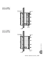
Page 400: ...49170 Israel Tel 972 3 9262000 Fax 972 3 9262310 http www tadirantele com USA Headquarters Tadiran Telecom Inc 265 Executive Dr Suite 250 Plainview NY 11803 Tel 1 516 632 7200 Fax 1 516 632 7210 Coral...

Reviews: