Lucid Series RF Signal Generator
Benchtop User Manual
Rev. 1.4
18
3
Benchtop GUI
3.1
CW Tab
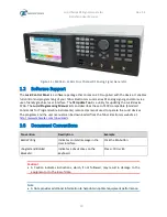
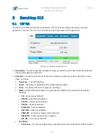
The CW (Carrier Wave) tab becomes available on the front panel display after power-up of the
generator. From here the user can set the basic output parameters of the generator.
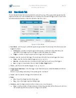
Figure 3.1 CW & Modulation Tab
•
Channel Bar
–
The bar shows the available channels and which channel that is selected. Selected
channel is denoted by a bold font.
•
Status
Bar
–
The bar at the bottom of the screen displays a summary of the system status and is
shown in all tabs.
⧫
Frequency
–
The CW frequency.
⧫
Power
–
The power (amplitude) of the output signal (in dBm).
⧫
Phase
–
The phase offset of the signal (0
–
360 deg.).
⧫
Mode
–
Shows which modulation is on (press Mode ON/Off in the respective modulation
window).
▪
CW
–
Carrier wave (default)
▪
AM,ON
–
Amplitude modulation
▪
FM, ON
–
Frequency modulation
▪
PM, ON
–
Phase modulation
▪
PULSE ON
–
Pulse modulation
▪
PATT,ON
–
Pattern modulation
▪
FRSW,ON
–
Frequency sweep mode is selected.
▪
PRSW,ON
–
Power sweep mode is selected.
▪
LIST,ON
–
List mode is selected.
⧫
Run Mode:
▪
Continuous
–
The device will generate a signal when the user clicks the RF OUT On button.

