TMA Q Series Getting Started Guide
3 1
Ethernet Switch Setup
In order to connect the instrument to a network, you will need to make the necessary cable connections as
described below. The instrument and controller will be connected to an Ethernet switch. In addition, there are
instructions for connecting the controller to a LAN.
Connecting the Instrument to the Switch
1.
Locate the Ethernet port on the left rear of the instrument (shown in
the figure to the right).
2.
Connect one end of the Ethernet cable into the instrument's Ethernet
port.
3.
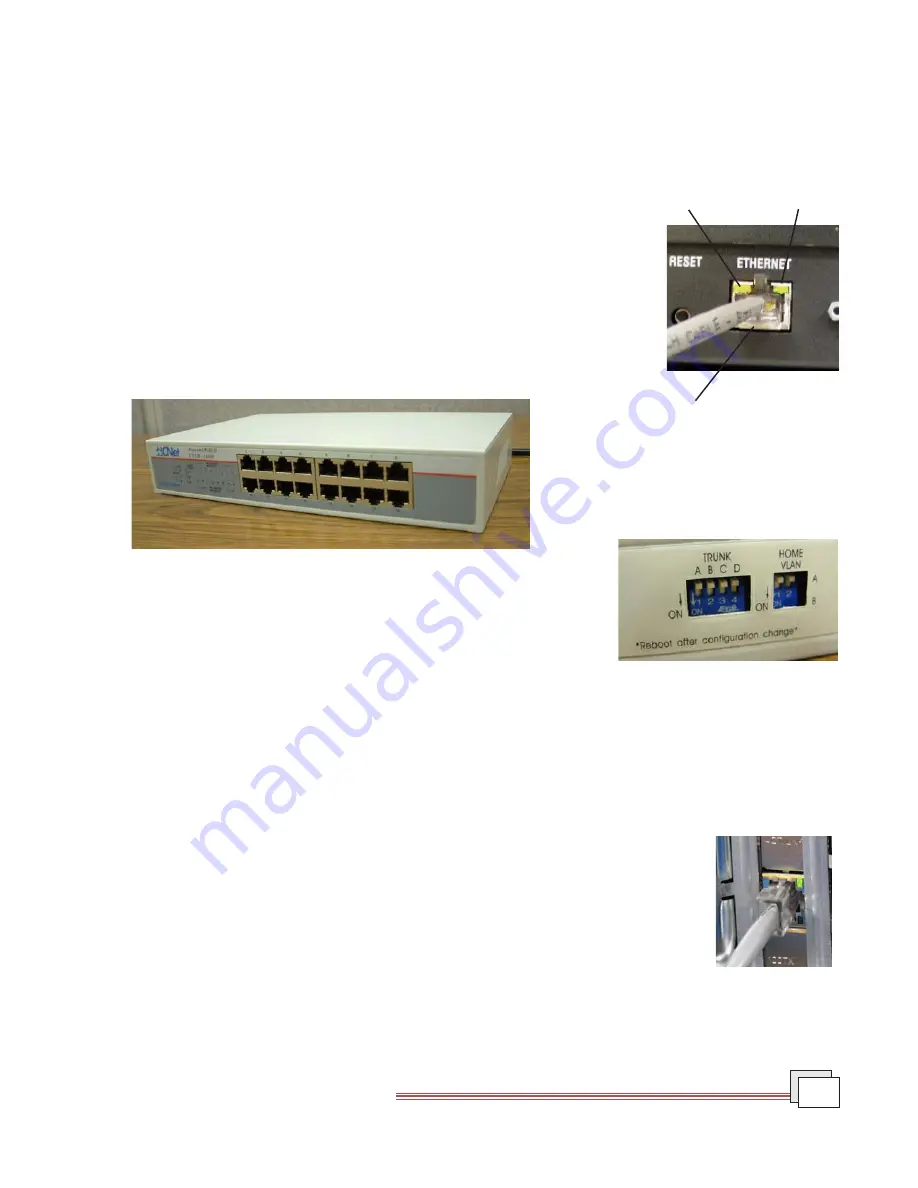
Connect the other end of the Ethernet cable to one of the network ports
on the Ethernet switch (shown in the figure below).
4.
Check the configuration switches, located on the back panel. They must
be set to off, or the up position, for the controller to communicate to the
instruments.
5.
Check the Ethernet port on the rear of the instrument. If communica-
tion between the instrument and the switch has been properly estab-
lished, a solid green light and flashing yellow light will appear at the port.
6.
Follow the directions in the next section to connect the controller to the Ethernet switch.
Connecting the Controller to the Switch
1.
Locate the Ethernet port on the back of the computer.
2.
Plug one end of the Ethernet cable into the computer's Ethernet port (shown in the
figure to the right).
3.
Connect the other end of the cable to one of the network ports on the switch.
4.
Check the Ethernet port on the rear of the computer. If communication between the
computer and the switch has been properly established, a solid green light and
flashing yellow light will appear at the port.
5.
Follow the directions in the next section to connect the controller to a LAN for net-
working capabilities.
Ethernet Connection
Yellow Light
Green Light
Configuration Switches
Ethernet Switch
Computer
Ethernet Port


