background image

136

WEB Interface

CP560 DVB-T2 Gateway User’s Manual Rev. 2.2 (3686)

ID: um_t2gateway

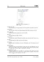
interface, double click on the appropriate line in the table. This opens the configuration page,
which may also be directly accessed by clicking on the IP output interface entry in the navigator
field (

Figure 8.66

). This is described in detail in

Section 8.6.6.1

.

Removing an IP output interface is accomplished by highlighting the appropriate line in the
table and clicking the

Remove IP Dest

button followed by

Apply

.

8.6.6 TS-OUT -

>

IP Destination

This page allows configuration of the IP output port. This page consists of the sub tabs

Main

and

Ping

. If Forward Error Correction has been enabled the

FEC

tab is also visible.

8.6.6.1 Main

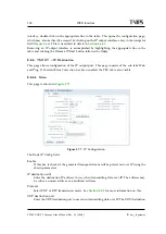
This page is shown in

Figure 8.77

.

Figure 8.77

IP Configuration.

The

Basic IP Config

field:

Enable

If this box is checked, the generated transport stream will be played out over IP using the
shown parameters.

IP destination addr

Enter the destination IP address to use when transmitting data over IP. The address may
be either a unicast address or a multicast address.

Protocol

Select UDP or RTP transmission mode. See

Section 5.5.2

for more information on this.

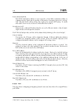
UDP destination port

Enter the UDP destination port to use when transmitting data over IP. The UDP destination

Summary of Contents for CP560

Page 1: ...CP560 DVB T2 Gateway User s Manual Revision 2 2 3686 2012 09 03 Valid for SW version 2 2 0 and newer...

Page 2: ......

Page 3: ...supply 19 4 5 1 AC power supply 19 4 5 1 1 AC power cable 19 4 5 1 2 Protective Earth technical Earth 19 4 5 1 3 Connecting to the AC power supply 20 4 5 2 DC power supply 20 4 5 2 1 DC power cable 2...

Page 4: ...35 7 2 1 Resetting the password list 36 7 3 Changing the IP address of the unit 36 7 3 1 Changing IP address via the Web GUI 36 7 3 2 Changing the management port IP address via terminal interface 37...

Page 5: ...s 86 8 4 10 GUI Preferences 87 8 5 Inputs 88 8 5 1 Inputs Overview 88 8 5 1 1 IP Inputs 89 8 5 1 2 Switch Inputs 91 8 5 2 Input 92 8 5 2 1 Main 93 8 5 2 2 Alarms 95 8 5 2 3 IP 99 8 5 2 3 1 IP Configur...

Page 6: ...5 9 4 1 Community strings 145 9 4 2 Trap destination table 146 9 4 3 Trap configuration 146 9 5 Alarm status related SNMP TRAPs 147 9 5 1 The main trap messages 147 9 5 2 Severity indications 147 9 5...

Page 7: ...erial USB interface 169 B 5 Alarm ports 169 B 5 1 Alarm relay reset port specification 169 B 6 External reference 170 B 6 1 10MHz 1 PPS input 170 B 7 Compliance 170 B 7 1 Safety 170 B 7 2 Electromagne...

Page 8: ...185 E 1 1 T2 Base 185 E 1 2 T2 Lite 186 E 2 Physical Layer Pipe 186 F Estimated Transmission Time 187 F 1 How the CP560 uses the configured ETT value 187 F 1 1 Example with 2 modulators 187 F 2 Implic...

Page 9: ...description Added DVB T2 MIP feature description Added individual addressing functions description Updated screenshots of the GUI 1 12 0 2011 02 02 Added Joint bit rate control feature description Add...

Page 10: ...10 CP560 DVB T2 Gateway User s Manual Rev 2 2 3686 ID um_t2gateway...

Page 11: ...will be provided The manual covers the following topics Getting started Equipment installation Operating instructions WEB interface description Preventive maintenance and fault finding Alarm listing T...

Page 12: ...tions should be read before this product is in stalled and operated All operating and usage instructions should be followed The safety and operating instructions should be retained for future referenc...

Page 13: ...control and timing information for the DVB T2 modulators 3 1 Summary of Features Features of the CP560 include Transport Stream TS encapsulation in T2 MI packets Single or Multiple Physical Layer Pipe...

Page 14: ...and control WEB XML based remote control Easy access to unit from any WEB browser Easy integration to NMS systems with SNMP Trap support SNMPv2c agent Equipment monitoring from T VIPS Connect Transmi...

Page 15: ...er of PLPs Physical Layer Pipes Number of input ports activated 16 Controls the number of simultaneously activated transport stream inputs Joint bit rate control Controls if the Joint Bit Rate Control...

Page 16: ...16 CP560 DVB T2 Gateway User s Manual Rev 2 2 3686 ID um_t2gateway...
Page 17: ...pply option Power cord s CD ROM containing documentation and Flash Player installation files Any optional accessories you have ordered Note 48 VDC versions do not ship with a power cord instead a Powe...

Page 18: ...contained in this unit are not fitted with dust insect filters Pay particular attention to this when considering the environment in which it shall be used Make sure that the equipment is adequately v...

Page 19: ...rds should be routed so that they are not likely to be trod on or pinched by items placed upon or against them Pay particular attention to cords at plugs and convenience receptacles The unit is suppli...

Page 20: ...rthed this way 2 Eliminate the migration of stray charges when interconnecting equipment Warning If the terminal screw has to be replaced use an M4x12mm long pozidrive pan head Using a longer screw ma...

Page 21: ...s soldering iron or a hot air workstation to attach the supplied female D SUB power connector to suitable power leads 2 Connect the power leads to your local power supply 3 Connect the DC power connec...

Page 22: ...22 CP560 DVB T2 Gateway User s Manual Rev 2 2 3686 ID um_t2gateway...

Page 23: ...ription of the different blocks is provided in following sections Inputs Processing Output Remote Control Configuration Alarm Log Alarm traps TS piping 1PPS SNTP ASI Input Optional IP T2 Gateway Modul...

Page 24: ...the same functionality as the ASI input ports and content received will be available to the DVB T2 Gateway generating the output The input streams can be either SPTS or MPTS and streams with or withou...

Page 25: ...es are generated accordingly to the settings defined in the user interface The DVB T2 packet bitrate is kept constant by the time source or the 1PPS signal this prevent the overflowing of the buffer o...

Page 26: ...down time on the unit due to incompatible configuration settings Configurations can be imported and exported via the GUI It is possible to clone the entire con figuration of one device to another by...

Page 27: ...s that have occurred As an additional option the alarm manager in the CP560 supports so called Virtual Alarm Relays These are highly programmable items that can be customised to react to virtually any...

Page 28: ...28 CP560 DVB T2 Gateway User s Manual Rev 2 2 3686 ID um_t2gateway...

Page 29: ...ATA SFP DATA 1 USB Main output port SFP Port USB Port Ethernet Data Ports Alarm Reset Interface 1PPS Input Mains Power Connector Technical Earth output copy Ethernet Management Port LED replica of fro...

Page 30: ...ATA 2 DATA SFP DATA 1 USB Inputs Ouputs Mains Power Connector Technical Earth 1PPS Input For optional SFN operation Alarm Reset Interface LED replica of front panel Ethernet Management Port Ethernet D...

Page 31: ...ASI output Some of the other ports can be configured as copies of the principle output as shown in chapter 6 1 2 One LED is used for each ASI output port A green LED is lit whenever the output is ena...

Page 32: ...th point 6 1 11 Alarm Reset The unit is equipped with a 9 pin male DSub connector to provide alarm information Two programmable relays are provided The first relay is always activated on a critical al...

Page 33: ...mon 3 Relay 2 Open on alarm NO 4 Prepared for 5V Output 5 Ground 6 Alarm Relay Closed on alarm NC 7 Alarm Relay Common 8 Alarm Relay Open on alarm NO 9 Optional Reset Input GPI For more details regard...

Page 34: ...34 CP560 DVB T2 Gateway User s Manual Rev 2 2 3686 ID um_t2gateway...

Page 35: ...able for the network where the unit will operate Initially therefore the user should change the IP address of the management interface so that access may be gained from the network The CP560 offers tw...

Page 36: ...7 3 1 Changing IP address via the Web GUI Changing the default IP address using the Web interface requires that your management com puter may be configured with a static IP address Note Avoid connect...

Page 37: ...device Note If several new devices are accessed one after another the ARP cache of the computer from which the devices are being accessed may have to be flushed between each device since the same IP...

Page 38: ...you have a prompt app 4 In the terminal type the following command and press Enter net ipconfig ip ip address mask subnet mask gw default gateway Example app net ipconfig ip 10 40 80 100 mask 255 255...

Page 39: ...formation 8 1 Login Access the CP560 by entering its IP address in the address field of your favourite browser When accessing the CP560 the first time the progress bar Figure 8 1 should appear while t...

Page 40: ...ising the header Using this hides a lot of the header information and gives more space for the rest of the page An activity indicator Note The activity indicator shows one box for each request being p...

Page 41: ...log and provides operations for clearing the log or exporting it as a comma separated value file CSV 8 3 1 Current Status Figure 8 5 Current status This page displays the current status of the device...

Page 42: ...ou can select which information to clear Current Alarms The bottom part of the page shows the currently active alarms Some alarms may contain several sub entries that are displayed by clicking on the...

Page 43: ...e alarm log was cleared The table consists of the same columns as the Current Alarms table but does not show details by default You can change which columns to show including the details column in Sec...

Page 44: ...to a comma separated value CSV file The button opens a file dialogue where the user can choose the destination to save the file on the computer Export to Browser Opens the complete log in a new browse...

Page 45: ...t This parameter together with the management network parameters are used as device identifiers and remain untouched if the unit configuration is changed by loading a different configuration file See...

Page 46: ...ly gives the build number Software build time Reports the time of which the current release image was built Device up time The amount of time that has passed since the device was last reset Internal t...

Page 47: ...the alarms The colour of the folder icon and the specific indicator represents the current status of the alarm The text to the right of the tree shows the currently configured severity of the alarm T...

Page 48: ...severity level can be configured In addition the alarms can be omitted from the alarm log and trap transmission Edited rows are highlighted until changes have been applied Tip For the Log and Send Tra...

Page 49: ...rates a specific alarm named Virtual alarm relay activated ID 169 The key element in the settings of the virtual relays is the Expression value The expression is very close to SQL in syntax and specif...

Page 50: ...r parentheses to group sub expressions together Together with the supported list of operators this gives great flexibility in constructing advanced match patterns Table 8 2 summarises the operator typ...

Page 51: ...es are required in the global alarm list 8 4 2 4 Alarm log settings This page is used to set alarm log properties Figure 8 12 Configuring the alarm log Log delimiter This parameter is used when export...

Page 52: ...sed as input source for a PLP the PLP id will be listed in the PLP column ASI inputs used as source for a PLP may not be port mapped to ASI outputs until it has been removed as source for the specifie...

Page 53: ...re the time zone of the unit Status The status of the time synchroniser Active The time source currently in use by the time synchroniser The Manual Adjust Time field allows the operator to set the tim...

Page 54: ...nable or disable the time source Disabled time sources are never updated Time sources configured and present in the prioritised list must be removed before they can be disabled IP address Specifies th...

Page 55: ...ured for this interface Link Speed The current link speed detected for this interface Applicable to physical interfaces only Duplex Mode The duplex mode detected for this interface half or full duplex...

Page 56: ...the physical interface Caution Modifying the settings of the interface you are currently using for the GUI application may cause loss of contact with the unit Make sure you will still be able to conta...

Page 57: ...Applies to the Control interface only These two boxes enable read and write attributes of the T VIPS Detect IP assignment server module This server is a stand alone PC application that can be used to...

Page 58: ...s not possible to enable data traffic on the management interface Multicast router This parameter is not shown in the management interface page The IP address of the multicast router The address here...

Page 59: ...nsmitted packets bitrate The total bitrate received transmitted load Interface load measured relative to max speed Total packets The total number of IP packets received transmitted Good packets The nu...

Page 60: ...s active It displays information provided by the SFP module installed 8 4 5 1 5 VLAN Figure 8 20 VLAN configuration This page is only shown on interfaces with VLAN virtual interface support The page a...

Page 61: ...efresh buttons there are buttons to enable adding and removing VLANs 8 4 5 1 6 SFP The SFP tab is visible for the second network interface if this interface is set to use SFP How to enable the SFP is...

Page 62: ...face CP560 DVB T2 Gateway User s Manual Rev 2 2 3686 ID um_t2gateway Figure 8 21 The Device Info Network SFP tab Figure 8 22 The SFP status page Vendor Shows the vendor name Revision Indicates the mod...

Page 63: ...as read back from the module The field heading will reflect whether a STM 1 OC 3 or an E3 T3 module is installed A discussion of the parameters shown is included in the Config pages description The M...

Page 64: ...ipolar Violation LCV Line Coding Violation LOS Loss of Signal RDI Remote Detection Indication WLD WAN Loop Detected EZ Excessive Zeroes PCV P bit Coding Violation OOF Out of Frame LLD Lan Loop Detecte...

Page 65: ...this will flush all error counters The STM 1 OC 3 Config page The STM 1 OC 3 module provides an optical interface for high speed data communications in SDH or SONET networks This page provides access...

Page 66: ...o enable FCS error detection Disable interface Not available Scrambler Tick this box to enable the module internal scrambler Must be ticked to successfully receive scrambled network data Ethernet flow...

Page 67: ...s of the configuration page The status of the SFP module is at all times displayed in the SFP Status sub page The E3 T3 Config page The E3T3 module provides an electrical interface for high speed data...

Page 68: ...the received data stream Line code Must be HDB3 for an E3 interface Select between B3ZS and AMI for a T3 interface Line length Only applicable for a T3 interface Allows the output signal to be adjust...

Page 69: ...enables flow control of Ethernet data from the CP560 to the SFP module Flow control prevents data overflow in the SFP module buffer Buffer overflow leads to data loss that would go unnoticed until att...

Page 70: ...to module box has not been ticked Clicking this button returns the module to factory default settings This will not affect the settings of the configuration page The status of the SFP module is at all...

Page 71: ...uting rules The receiving interface must have management traffic enabled to forward TCP traffic to a different interface Note Modifying the IP routing rules may cause loss of contact with the unit Mak...

Page 72: ...t path dev time _select uptimetxt response request_id 0 method txp_get time_stamp 2012 08 17 11 14 20 version 1 0 status status 0 status_text OK data dev time uptimetxt 49 days 21h 56m 09s dev data re...

Page 73: ...are still transmitted Basic The device forwards alarm events as SNMP traps If there are several sub entries only a single trap is transmitted Detailed The device forwards alarm events as SNMP traps If...

Page 74: ...Values range from 1 to 255 Ping count The number of ping messages to send The messages are transmitted with an interval of about 1 second Start Press this button to start the pinging sequence configu...

Page 75: ...internal clock will not make use of an external reference signal Lock to external 1 PPS Configures the internal clock to use the external 1 PPS input connector as reference The Clock Regulator Status...

Page 76: ...anaged locally not including the current running configuration 8 4 7 1 Save Load Configs This is the interface for exporting the current running configuration as an XML file Clicking the Save Config b...

Page 77: ...om the administrator s PC to the device Validates the configuration to make sure that all the options in the file are compatible with each other and with the device itself Presents the user with addit...

Page 78: ...ill not be replaced This page may then be inspected to find the reason for rejection 8 4 7 3 Stored Configs This page provides an interface to management on device stored configuration snapshots Up to...

Page 79: ...ttons are provided to perform actions on the snapshots Activate Loads the selected snapshot as the active configuration of the device The administrator will be prompted to verify the decision as this...

Page 80: ...determine the switch position The Emergency Switch tab provides the means to configure the behaviour of the CP560 under emergency switch control Figure 8 33 Emergency switch The table lists the rules...

Page 81: ...has the following parameters Enabled A tick in the box enables this rule Description User defined description of the rule Ip The IP address of the emergency switch unit Active configuration The ID of...

Page 82: ...o discard changes and close the pane 8 4 8 Maintenance The Maintenance page centralises information regarding the hardware configuration of the de vice and provides a means for updating firmware image...

Page 83: ...the unit Serial number The manufacturer assigned serial number used for warranty and software licensing Installed boards The name and serial numbers of the circuit boards installed in each of the int...

Page 84: ...used to allocate the Data 2 IP input to operate through the Electrical Ethernet data interface or through the SFP slot Figure 8 37 SFP and Electrical Ether net select When switching mode the unit will...

Page 85: ...with the Details field displaying the IP address of the machine from which the loading was initiated The alarm is turned off when the loading is completed or terminated If the Reboot on success option...

Page 86: ...ssword for each privilege level and for configuring automatic login settings You must have administrator previledges to alter the settings Auto login Specifies the user privilege level to use for auto...

Page 87: ...to the device 8 4 10 GUI Preferences Figure 8 41 GUI Preferences page The GUI Preferences page contains settings that affect the web interface Enable confirmation on Apply Configures the web UI to pro...

Page 88: ...n of the user defined name of the input and the physical number of the input port 8 5 1 Inputs Overview Figure 8 42 Inputs Overview The Inputs Overview page shows a short table summary of all the inpu...

Page 89: ...ts The Reset Stats button at the bottom of the page gives access to a dialogue box that allows reset of channel statistics Figure 8 43 shows the dialogue box Select the statistics items you want to re...

Page 90: ...ate The currently received bitrate in Mbit s measured at the Ethernet level Seq Err The number of RTP sequence errors reported by the input since the last reset of statistics RTP sequence error measur...

Page 91: ...e The page lists the defined input switches and offers controls to add and remove switch inputs Figure 8 45 Inputs Overview Switch Inputs Columns in the grid are Enable This shows whether the switch i...

Page 92: ...rt of the page is common for all sub pages and shows the name and the current alarm status of the input Figure 8 46 Input header Holding the mouse cursor over the alarm status indicator brings up a to...

Page 93: ...s divided into three sections the first one being the Transport Stream De tails field This field contains information and some configuration parameters concerning the transport stream Enable input Thi...

Page 94: ...ransport Stream Details section is the PIDs present section This shows all the PIDs that are present on the selected input The number in parentheses is the total number of PIDs present A PCR PID is re...

Page 95: ...he service is displayed by holding the mouse pointer over the I icon to the right Service Bitrate The current bitrate of the service i e the aggregate bitrate of all the service components Double clic...

Page 96: ...y alarm settings for a specific input to the current input Use the Input drop down list to choose from which input to copy the settings The settings are copied by hitting the Copy Settings button This...

Page 97: ...details section includes the following information and buttons Alarm ID The internal ID of the selected alarm A complete list of alarms is found in Table G 3 Description A short description of the al...

Page 98: ...larm severity level is set to global default in the Severity pull down list this is the value that will be used In addition if the alarm contains a limit e g max interval a numeric input at the bottom...

Page 99: ...ew severity The new severity i e the severity after the sub item has been overridden New limit If the alarm has a configurable limit also the limit of the sub item can be overridden and that new limit...

Page 100: ...is the multicast group the input will join Multicast source addr This parameter will only be used if the input is set to join a multicast and the unit is cur rently using IGMP v3 If this parameter is...

Page 101: ...IP frames A counter showing the number of IP frames corrected by the FEC engine Max burst loss The maximum number of consecutive packets lost Number of resyncs The number of times the buffer has been...

Page 102: ...IP frames that have been lost Columns L The number of columns used in the FEC matrix of the incoming signal Rows D The number of rows used in the FEC matrix of the incoming signal Max IP frames delay...

Page 103: ...able Unicast Peer Ping This enables regular pinging of the transmitting device Interval Set the interval in seconds between each Ping The Status field displays the status of the on going pinging sessi...

Page 104: ...in the Max VBR bitrate input If the incoming rate is higher than this a buffer overflow alarm will be triggered FAST COARSE In this mode the units attamps to set up the regulator very fast on the expe...

Page 105: ...imate is found the regulator switches to Coarse mode where the output bitrate is coarsely moved closer to the new rate From Coarse mode the regulator enters Finetune mode Initial bitrate Here the exac...

Page 106: ...igator to the right of the list con taining more information about the selected service The Details tab shows detailed information about the selected service The service information may be presented i...

Page 107: ...rmation is signalled to be present for this service This information is extracted from SDT actual Scrambling signalled Whether scrambling is signalled for the service Interpretation of the Free_CA bit...

Page 108: ...ws a tree containing all SDT descriptors if present To list all components contained within a specific service click the arrow for the given service The expanded view is shown in Figure 8 57 Figure 8...

Page 109: ...the selected component 8 5 2 5 PIDs This page gives detailed information about the PIDs present on the input Two different PID views may be selected with buttons on the tool bar at the top of the pag...

Page 110: ...bit s since the last rate reset CCErr Cnt This is a counter which shows the number of Continuity Count errors on this packet stream since the last CC error count reset Ref by Service This is a list of...

Page 111: ...rop down menu on top lets the user sort the bar chart by different parameters The Filtering frame lets the user choose which PIDs to show Checking the Hide null PID check box removes the null PID from...

Page 112: ...contains a tree showing the tables that are present on the input and analysed by the device The tables belonging to a specific folder are displayed to the right by clicking on the folder Above the tab...

Page 113: ...the table opens a view displaying the parameters of that table The parameters are the same as are shown in the table view 8 5 2 8 Settings In this sub page it is possible to select the table types to...

Page 114: ...alysis configuration Figure 8 63 Table analysis configuration in ATSC mode To see the service name for the services you have to configure analysis of SDTa SDT actual for DVB services or TVCT CVCT for...

Page 115: ...out parameter and selecting Set to default resets the original value The timeout values are also used to generate Table missing alarms 8 5 2 9 Sources Figure 8 64 Non standard table source PID configu...

Page 116: ...in section Section 8 3 1 8 5 3 1 Main Figure 8 65 Input switch configuration The Main sub page is used to configure input switching of a group of inputs The page is accessed by selecting a switch in t...

Page 117: ...currently 0 5 seconds Set this to 0 for fastest possible switching Return wait Return wait activated when switching away from a port It will not be possible to return to a port before Return wait sec...

Page 118: ...t time has passed 8 5 3 2 Alarms The Alarms sub page allows the user to configure the alarms for the input switch It works identically to and is described under Device Alarms in section 8 4 2 1 8 6 Ou...

Page 119: ...s on this output are displayed in a tool tip by holding the mouse cursor over the alarm status indicator The right section consists of a utilisation bar and a number showing the total rate that is cur...

Page 120: ...lly by the unit If automatic mode is selected the CP560 will always select the minimum bitrate needed for the T2 MI stream thus reducing the number of stuffing packets PID 8191 to zero Set output bitr...

Page 121: ...nsmit the transport stream packets on this output burst mode or spread mode Packet length This lets the user configure the output to transmit 188 or 204 byte transport stream packets Reed Solomon FEC...

Page 122: ...or 1 3 1 makes the CP560 signal High Efficiency and Normal Mode in the L1 signalling It also gives a different selection of PAPR techniques The following settings define the structure of the T2 Frame...

Page 123: ...ally only one entry is required Note that some modulators override this setting L1 modulation This field indicates the used modulation for the L1 signalling Possible values are Binary Phase Shift Keyi...

Page 124: ...ry When synced the T2 Timestamp seconds field will be based on the SNTP time while the subsecond field will be synchronized to the external PPS Note Please wait a few seconds for the resync to take ef...

Page 125: ...CP560 in a Seamless SFN system leap seconds must be handled If not leap seconds may be ignored Leap seconds since 2000 This is the current amount of leap seconds accounted for since 2000 This value w...

Page 126: ...on will be given when the leap seconds is added This notification can be seen in the alarm log see section 8 3 2 8 6 4 3 PLP configuration The PLP configuration page has all the PLP configuration para...

Page 127: ...exceed the total capacity of the T2 Frame If so a warning will be given when pressing Apply If so the Requested bitrate must be decreased or the number of bits per symbol increased or the total T2 Fra...

Page 128: ...re Amplitude Modulation 16 QAM 64 Quadrature Amplitude Modulation 64 QAM 256 Quadrature Amplitude Modulation 256 QAM Rotated constellation This feature improve the avoidence of potential problems in s...

Page 129: ...y through receiver buffer to handle dejitter and deinterleaving Only available when using ISSY Settings this value slightly larger than the T2 Frame duration should handle most cases Alternatively set...

Page 130: ...C blocks cells and subslices allocated for each PLP hover the mouse pointer over this field to get a tool tip as shown in figure 8 72 Figure 8 72 DVB T2 PLP Allocations At the bottom right of figure 8...

Page 131: ...umber append ed If the bit rate OID is 1 3 6 1 4 1 22909 1 3 2 1 1 1 7 and the instance is 7 this field must contain the string 1 3 6 1 4 1 22909 1 3 2 1 1 1 7 7 OID type The data type of the OID Read...

Page 132: ...erted into the outer TS layer or not PCR PID This field indicates the PID of the inserted PCR packets PCR interval This field indicates the distance between two PCR packets in ms The maximum value is...

Page 133: ...dulator is done by first pressing the Add button to add a new modulator Every modulator has different settings that are possible to edit The PAPR parameters ACE TR and L1 ACE are not mandatory and the...

Page 134: ...ignaling is to be sent User must specify value of Max correction ACE PAPR Select if individual addressing frame with ACE Active Constellation Extension parameter is to be sent User must specify Gain M...

Page 135: ...period If desired the duration of the FEF subpart TX SIG may be extended by setting the this field to a value greater than zero The unit is in Elementary Periods T See 10 DVB Document A150 for further...

Page 136: ...s configuration of the IP output port This page consists of the sub tabs Main and Ping If Forward Error Correction has been enabled the FEC tab is also visible 8 6 6 1 Main This page is shown in Figur...

Page 137: ...e to be set in the Type of Service TOS field in the IP header as specified in RFC 791 This parameter is used for Class of Service prioritisation Its usefulness depends on routers honouring this field...

Page 138: ...nation address is resolved The parameter is always Yes when multicast is used without a multicast router No when the MAC address is not yet resolved by ARP lookup Dest MAC address Shows the destinatio...

Page 139: ...FEC Configuration field allows setting of common parameters that will be applied to the FEC processor in general Number of columns L The number of columns used in generating the Row FEC data Number o...

Page 140: ...Ping Check this box to enable Unicast Peer Ping This enables regular pinging of the receiving device Interval Set the interval in seconds between each Ping The Status field displays the status of the...

Page 141: ...response is received Clicking the Clear Statistics button resets the counts in the Status field 8 6 7 Alarms The Alarms page lets the user configure and view the status of all alarms belonging to the...

Page 142: ...142 CP560 DVB T2 Gateway User s Manual Rev 2 2 3686 ID um_t2gateway...

Page 143: ...notifications are supported It is however recommend ed to use the new SNMPv2 notification types for new deployments 9 2 MIB naming conventions All custom MIB files start with the prefix VIGW MIBs that...

Page 144: ...it from entering an undefined intermediate state VIGW PLAT TS MIB This MIB contains Transport Stream related information for each of the transport stream inputs It is supported by transport stream rel...

Page 145: ...nd packet loss VIGW PLAT VIDEO MIB This MIB contains tables and settings to configure video specific processing It is support ed by products that relate to digital video streams for example JPEG2000 b...

Page 146: ...storical reasons and it is not recommended to use these for new deployments SNMPv2 This is the recommended setting The traps defined under the node unitNotifi cations will be used while the traps unde...

Page 147: ...red This trap is sent when an alarm condition previously indicated with unitAlarmAsserted is cleared unitAlarmEvent This trap is sent when an alarm event with no on off state is generated No correspon...

Page 148: ...boards it is typically set to a fixed value 0 or 1 and can be ignored unitEventSubId2 This field s purpose is dependent on the alarm type alarm id For some alarms it is not used and set to zero For o...

Page 149: ...format of these traps follow the SNMPv1 trap format In contrast to the SNMPv2 alarm messages the SNMPv1 messages has its severity implicitly encoded in the trap type The trap messages are defined in...

Page 150: ...150 CP560 DVB T2 Gateway User s Manual Rev 2 2 3686 ID um_t2gateway...
Page 151: ...ure a time zone and a source for the real time clock to assure alarm log entries get correct time stamping See section 8 4 4 5 Connect the input signal to the 1 PPS input 6 On the Clock Regulator tab...

Page 152: ...imestamp type Null Estimated transmission time 1000 PLP configuration PLP Settings Input port ASI 1 Payload type TS PLP mode High Efficiency Group id 0 Modulation 256 QAM Rotated constellation Enabled...

Page 153: ...ld take into ac count all delays buffers from the CP560 to the transmission time in the modulator Current suggestion 500 ms 150 ms modulator processing time 250 ms network delay 100 ms extra buffering...

Page 154: ...6 4 4 Also required for seamless operation in the T VIPS TNS541 where the PCR packets could affect the seamless switching operation 6 Use Relative or Absolute DVB T2 Timestamps see section 8 6 4 1 7 M...

Page 155: ...ffected The CP560 has an option to set the Transport Error Indicator in the Transport Stream header of the T2 MI PID if any of the PLPs are empty If this flag is set the TNS541 will be able to detect...

Page 156: ...156 CP560 DVB T2 Gateway User s Manual Rev 2 2 3686 ID um_t2gateway...
Page 157: ...soft cloth dampened with a mixture of mild detergent and water Make sure that the unit is completely dry before reconnecting it to a power source 11 1 3 Servicing Warning Do not attempt to service th...

Page 158: ...ot be attributed to other system components This manual does not provide any maintenance information or procedures which would require removal of covers Warning Do not remove the covers of this equipm...

Page 159: ...equipment if it becomes unusable or to protect it from further damage 11 2 2 PSU LED not lit power supply problem Power fault finding 1 Check the Power LED Is the LED unlit but the unit still working...

Page 160: ...dule to the suspect fan s Call a Service Engineer 11 3 Disposing of this equipment Dispose of this equipment safely at the end of its life time Local codes and or environmental restrictions may affect...

Page 161: ...es a mecha nism for the network to give e g video traffic higher priority than other traffic for example Internet traffic DVB Digital Video Broadcasting The European consortium defining standards for...

Page 162: ...or a host receiver unit to receive a multicast it needs to transmit IGMP join messages in the right format Three versions exist IGMPv2 is commonly used today but IGMPv3 is the next step JPEG2000 A wav...

Page 163: ...smitter and receivers PID Packet Identifier An 11 bit field in an MPEG2 transport packet defining a logical channel 8192 unique logical channels may coexist in one network PSI SI PSIP Program Specific...

Page 164: ...a SDTV Standard Definition Television The normal television standard resolution in use today SFP Small Form factor Pluggable module A standardized mechanism to allow usage of various electrical or opt...

Page 165: ...been taken over and reused by DiffServ Transport Stream TS The common name for an MPEG2 Transport Stream A bit stream used to carry a multiplex of packets each identified by a unique Packet Identifie...

Page 166: ...166 CP560 DVB T2 Gateway User s Manual Rev 2 2 3686 ID um_t2gateway...
Page 167: ...ing connectors Overall depth 340 mm including connectors Approximate weight 2 5 kg Rack mount case 19 inch width 1 U height B 2 Environmental conditions Table B 1 Environmental specification Operating...

Page 168: ...e terminal 2 middle negative terminal 3 bottom Chassis Ground B 4 Input output ports B 4 1 DVB ASI port Table B 5 ASI Port Specification Type ASI C Coaxial cable Connector type BNC 75 socket Signal Co...

Page 169: ...ot to carry copper or optical SFP compatible with approved modules conforming to the Small Form factor Pluggable Transceiver Multi Source agreements Sept 14 2000 B 4 4 Serial USB interface Table B 9 U...

Page 170: ...s been designed to meet the following safety requirements Table B 12 Table B 12 Safety requirements met EN60950 European Safety of information technology equipment including business equipment IEC 609...

Page 171: ...3 23 EEC of 19 February 1973 on the harmonisation of the laws of the Member States relating to electrical equipment designed for the use within certain voltage limits 1999 5 EC of March 1999 on radio...

Page 172: ...172 CP560 DVB T2 Gateway User s Manual Rev 2 2 3686 ID um_t2gateway...

Page 173: ...ed to request retransmissions which in itself inflicts a bandwidth increase in a channel at the edge of overflow Accordingly all broadcast related IP traffic use UDP User Datagram Protocol Here no ret...

Page 174: ...ration with SMPTE successfully brought the COP 3 and COP 4 further and COP 3 is now finalised as SMPTE 2022 1 12 and 2022 2 11 SMPTE 2022 1 focuses on improving IP packet loss ratio PLR performance us...

Page 175: ...ociated with each column and it is therefore possible to regenerate as many packets as there are columns in the matrix In the right most panel of Figure C 2 the case is shown where a packet in the las...

Page 176: ...n equipment from different manufacturers One method is to offset the FEC columns one example is shown in Figure C 4 which also provides additional advantages Figure C 4 FEC matrix with column offset C...

Page 177: ...layer FEC and equipment without that capability FEC data is transmitted using UDP port numbers different from that of the payload Column FEC is transmitted using port number IP payload 2 and row FEC i...

Page 178: ...ible be regenerated by FEC There are three main factors that cause packet loss Occasional bit errors in the Ethernet frame caused by low noise margin or equipment fault Buffer overflow or packet delay...

Page 179: ...packet loss ratio of 1x10 6 Figure C 8 Recommended error performance as per ITU C 6 Error improvement So what does it take to make FEC improve the packet error rate of an IP network link to a level ac...

Page 180: ...case a 3Mbit s video transport stream in an IP net work with worst hour PLR of 3x10 3 a service with less than 10 error hits per day may be provided using any of the matrix sizes shown In less error...

Page 181: ...um allowable column depth of 4 will produce 25 overhead In two dimensional FEC there will be D L FEC packets in a DxL matrix L being the row length Thus the added overhead is D L DxL which for a 10 by...

Page 182: ...182 CP560 DVB T2 Gateway User s Manual Rev 2 2 3686 ID um_t2gateway...

Page 183: ...one according to the label and packets will be switched expediently The MPLS label is added to the IP packet by the ingress router and removed by the egress router The labelling is done on the basis o...

Page 184: ...ge from 0 to 255 D 3 Layer 2 priority Prioritisation can also be supported in layer 2 using VLAN tags The 802 1q VLAN tag has 3 bits for setting the Class of Service COS The operation is further defin...

Page 185: ...Valid Pilot Patterns for combinations of FFT size and Guard Interval 1 32 1 16 1 8 1 4 1 128 19 128 19 256 32k PP4 PP6 PP2 PP4 PP8 PP2 PP8 PP7 PP2 PP8 PP2 PP4 PP8 16k PP4 PP6 PP7 PP2 PP4 PP5 PP8 PP2...

Page 186: ...8 19 128 19 256 32k 16k PP6 PP7 PP4 PP5 PP2 PP3 PP1 PP7 PP2 PP3 PP2 PP4 PP5 8k PP4 PP7 PP4 PP5 PP2 PP3 PP1 PP7 PP2 PP3 PP4 PP5 4k PP4 PP7 PP4 PP5 PP2 PP3 PP1 2k PP4 PP7 PP4 PP5 PP2 PP3 PP1 1k Table E...

Page 187: ...t chapter 5 2 7 of 9 ETSI EN 102 773 F 1 How the CP560 uses the configured ETT value When the CP560 starts building a T2 Super Frame it samples and stores the phase of the current external reference 1...

Page 188: ...delay from the CP560 to each modulator in an SFN region Remember to account for possible jitter in your network especially if using IP trans mission 2 Find the required processing delay for each modul...

Page 189: ...larm to filtered so that there will be no alarm events generated for this alarm The WEB interface gives the most detailed alarm information as all active alarms and warnings are listed with time of oc...

Page 190: ...e grouped together into different types This field contains a textual description of the type Type ID Each alarm type has a corresponding number ID Clear event Set to Yes if an off cleared alarm is ex...

Page 191: ...es Type Ethernet port Type ID 17 Clear event Yes Subid2 Ethernet port ID 134 Ethernet link problem Critical Description Problem on the ethernet link Type Ethernet port Type ID 17 Clear event Yes Subid...

Page 192: ...ear event Yes 161 Too high temperature Warning Description Internal temperature of unit is too high Type System Type ID 13 Clear event Yes 162 Defective fan Warning Description One or more fans are no...

Page 193: ...tem Type ID 13 Clear event Yes 212 Emergency switch rule config error Warning Description An error has been detected in the configuration of the emergency switch Type System Type ID 13 Clear event Yes...

Page 194: ...D 13 Clear event No 520 SW loading in progress Notification Description Loading of an embedded SW image is in progress Type System Type ID 13 Clear event Yes 521 New SW pending Notification Descriptio...

Page 195: ...troller 534 JBRC bit rate set on source device Notification Description Joint bit rate controller successfuly set the bit rate on the source device Type JBRC Type ID 26 Clear event Yes Subid2 Joint bi...

Page 196: ...t Type ID 9 Clear event Yes Subid2 Port identifier 1152 PMT scrambled Warning Description See ETSI Technical Report 290 Type Port Type ID 9 Clear event Yes Subid2 Port identifier 1153 PMT missing Warn...

Page 197: ...error Type Port Type ID 9 Clear event Yes Subid2 Port identifier 1545 Empty PLP Warning Description PLP is not receiving data Empty PLP being output Type Port Type ID 9 Clear event Yes Subid2 Port id...

Page 198: ...h Alarms Alarm ID Text Def severity Details 1813 TS rate too low Filtered Description TS bitrate is lower than set limit Type Port Type ID 9 Clear event Yes Subid2 Port identifier 2100 PSIP repetition...

Page 199: ...d Audio in Satellite and Cable Broadcasting Applications ETSI Technical Report ETR 154 European Telecommunications Standards Institute ETSI 7 IEEE 802 1Q 2005 802 1QTM Standards for Local and metropol...

Page 200: ...et protocol aspects Quality of service and network performance Network performance objectives for IP based Services 14 Pro MPEG Forum Pro MPEG Code of Practice 3 release 2 July 2004 Transmission of Pr...

Reviews: