19
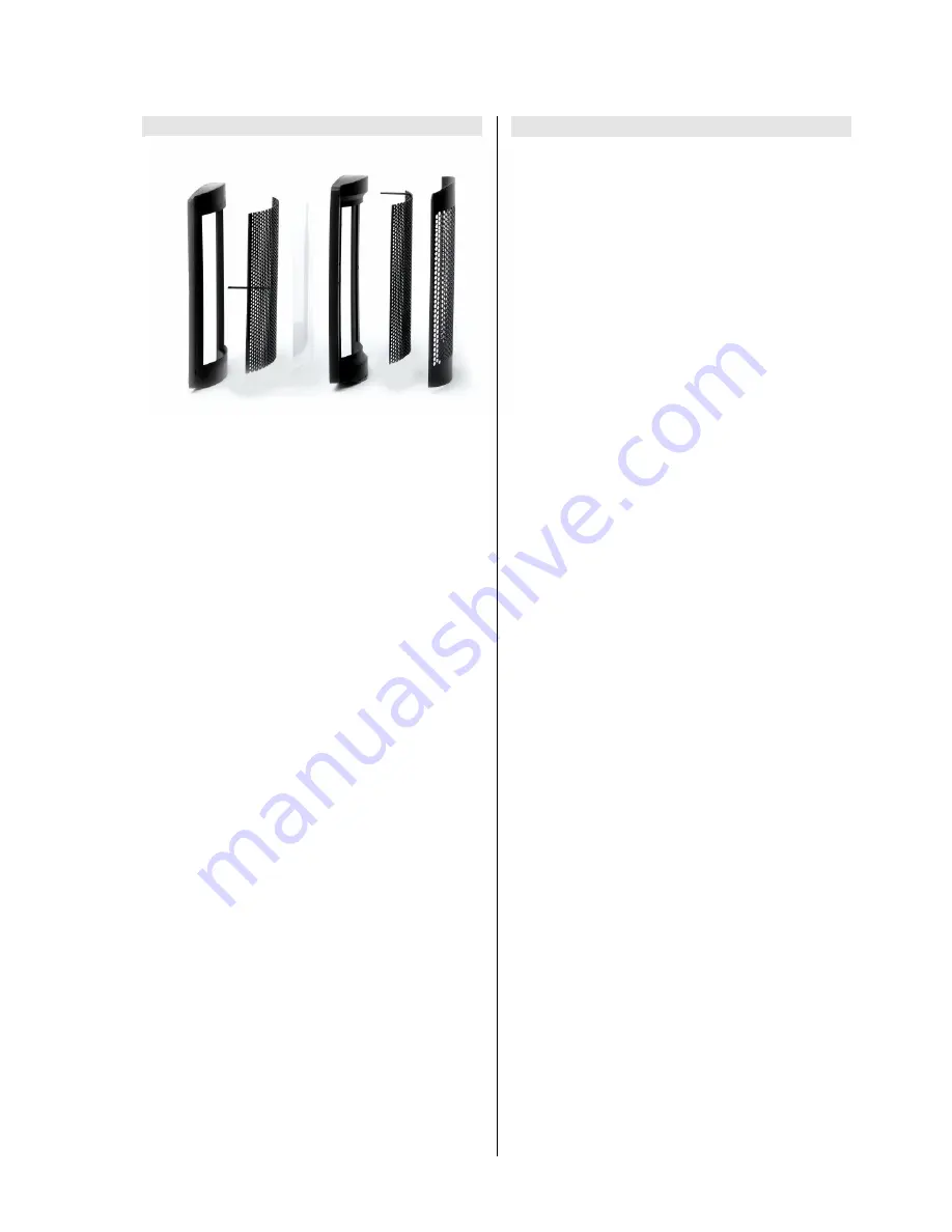
The electrostatic treble unit
Electrostatic units are amongst the oldest loudspeaker
technologies. In its basic form a featherlight membrane
(in our electrostatic units only a few µm thick) is charged
electrically and held between two electrodes, to which
the music signal is fed at a high voltage.
The foil is driven homogeneously over its entire surface,
and for this reason is free of any tendency towards
partial vibration. With its low mass the foil is practically
inertia-free, endowing the electrostatic device with a
virtually perfect transient response. The extremely high
upper limit frequency (> 70,000 Hz) of these systems is
almost beyond the reach of conventional dynamic
loudspeaker systems.
These are the reasons why
has developed an
electrostatic treble unit, which is built using sophisticated
precision tooling. In this speaker the potential
advantages of all electrostatic drivers - superb dynamic
characteristics, transparency, lightness and luminosity -
are brought fully to fruition.
The curvature of the foil membrane produces a linear
frequency response even under large off-axis listening
angles of up to +/- 30°.
Electrostatic drivers require a power supply to charge up
the foil membrane, and that is why the
TCI C2
features a
mains power input. In the
TCI C2
the amplifier signal is
driven to high voltage using a repeater.
The cross-over unit
A very sophisticated, low-loss passive FSR cross-over
unit (FSR =
F
ast
S
ignal
R
esponse) adjusts the
combination of electrostatic unit and repeater (
TCI C2
),
to match the output of the other sub-systems in the
loudspeaker.
The circuit boards of these cross-over units feature a
large-area copper layer on the top surface whose sole
purpose is to act as the earth conductor.
The copper tracks on the underside connect the
components with each other. This layout ensures that the
critical earth reference potential is not falsified by the
large signal currents which flow. The usual voltage
losses caused by narrow conductor tracks do not occur
in this design, which means that much higher currents
can safely be used. Undesired effects on signals such as
inter-modulation or cross-talk between the individual
tracks are also minimised.
The components of the cross-over unit are extremely
low-resistance types, and are designed to minimise
losses.
The large capacitance required is implemented in the
form of several small capacitors wired in parallel, as this
arrangement reduces series inductivity and resistance,
and also improves slew rates. All these design features
are aimed at obtaining maximum possible signal fidelity.
To reduce the distortion which can arise with large
currents, virtually all the coils are of the air-core type.
High-quality
cable is employed for all internal wiring
inside the cabinets.
Summary of Contents for TCI S 3
Page 1: ...Bestell Nummer Order No 9103 0322 TCI C2 TCI S3 BETRIEBSANLEITUNG USER MANUAL TCI C 2 TCI S 3...
Page 2: ...2...
Page 11: ...11...
Page 15: ...15 English...
Page 23: ...23...
Page 28: ...elektroakustik GmbH Co KG Herford Deutschland Germany...


