T+A Elektroakustik P 1230 R Service Manual Download Page 15

15

4.3Schutzschaltung (Protection)

Die Schutzschaltung der Endstufen besteht aus einer
Strombegrenzung und einer Schaltung zur Überwa-
chung des Ausgangssignals. Letztere spricht bei einer
Abweichung des Ausgangssignals vom Sollsignal
(Clipping, Verzerrungen etc.) an und schützt wirkungs-
voll die angeschlossenen Lautsprecher.  Desweiteren
wird die Endstufe auf Übertemperatur und Gleichspan-
nungsfehler am Ausgang überwacht.

4.3.1

Strombegrenzung

Der Ausgangsstrom wird über die Widerstände R746
bzw. R747 gemessen. Die Spannung an diesen Wider-
ständen führt bei Überstrom zu einem Durchschalten
der Transistoren T731 und T733 (BZW. T732, T734)
und damit zur Abschaltung der Endtransistoren.  Das
Ansprechverhalten der Strombegrenzung ist durch den
Spannungsteiler R734,R732,C732 (R735,R733,C733)
verzögert. Geringe, kurzzeitige Überlastungen führen
daher nicht zum Ansprechen. Da bei hohen Aussteue-
rungen höhere Ausgangsströme geliefert werden kön-
nen, ohne die SOA (Safe  Operating  Area) der Lei-
stungstransistoren zu verlassen ist die Strombegren-
zung über den Spannungsteiler R734,R720,D730
(R735,R729,D731) amplitudenabhängig. Dies verbes-
sert die Stromlieferfähigkeit an normaler Last erheblich.

4.3.2

Überwachung der Ausgangssignalform

Tritt in der Endstufe ein Fehler auf, der zu einer Signal-
verformung (Cipping, Klirr, HF-Schwingen etc.) führt, so
resultiert eine nennenswerte Differenzspannung am
Eingang (Pins 2,3) des  Endstufeneingangs-OPs
(IC701), was eine große Ausgangsspannung an die-
sem OP hervorruft.  Dieses Signal gelangt über die
Leitung "CLIP_PROT" zur weiteren Verarbeitung zum
IC501 (s. Netzteil).
Über die Leitung "DC_PROT" wird der Endstufenaus-
gang auf Offsetspannung überwacht.

4.3.3

Prüfung der Schutzschaltung

a)  Clipping

Die Schutzschaltung sollte bei 5..10 % Übersteuerung bei
einem 5 kHz Sinus Eingangssignal sicher ansprechen.  Bei 50
Hz Eingangssignal sollte eine kurzzeitige Übersteuerung (
<0.5s) noch nicht zum Ansprechen führen.
b)  Übertemperatur
Überbrücken des NTC Lötnägel Y516/517 muß zum sofortigen
Abschalten führen.
c)  Kurzschluß
Ein Kurzschluß am Ausgang mit Signal führt zur sofortigen
Strombegrenzung. Da dies ein  Signalclipping zur Folge hat
werden über die Clipping-Schutzschaltung auch die Ausgänge
abgeschaltet.  Die Steuerung schaltet bei Kurzschluß die Aus-
gänge periodisch wieder ein, um zu prüfen, ob der Kurzschluß
noch besteht.

Nach Beendigung der Auslösebedingung der Schutzschaltung
muß sofort das Blinken der Ausgangs-LEDs aufhören. Das
Gerät muß anschließend nach Ablauf einer kurzen Einschalt-
verzögerungszeit wieder normal einschalten.

The power amplifiers protection circuit consists of a
current limiter stage (short circuit protection) and a DC-
voltage / clipping protection.

4.3.1

Short circuit protection

The output current is sensed by the emitter resistors
(R746/R747) of the output transistors. A too high output
current results in a voltage across these resistors which
is above the base – emitter voltage of the transistors
T731/T733 or T732/T734 which causes these transis-
tors to conduct, leading to a shut-down of the output
transistors.

4.3.2

Clipping & DC Protection

If a fault in the power amplifier occurs, which leads to a
distortion of the output signal (clipping, ringing, oscilla-
tion etc.), a difference voltage at the inputs (pins 2&3)
of IC701 will be the result. This difference voltage will
be amplified and will occur at the output of IC701. This
signal is delivered through the line “PROT_CLIP” to the
protection circuit around IC501 for further processing
(see -> power supply).
Via the DC_PROT line the speaker output is super-
vised for any DC-voltage.

4.3.3

Testing the protection circuit

a)  Clipping
Driving the amplifier into 5...10 % clipping of the output
signal with a 5 kHz sine, should lead to a tripping of the
protection circuit after 10...15 seconds.

b)  Over temperature
Shorting the  overtemp.-NTC (Y516/Y517) on the heat
sink should lead to an immediate tripping of the protec-
tion circuit.

c)  Short circuit
Shorting the speaker terminals (with signal applied)
leads to immediate limiting of the output current and
thus to a severe distortion of the output signal. This in
turn leads to a tripping of the protection circuit after a
few seconds.

After removing the cause for tripping, the speakers
should switch ON again after approx 30 seconds.

Summary of Contents for P 1230 R

Page 1: ...Bestell Nr 9120 0052 T T Pre AMP Vorverst rker P 1230 R Integrated AMP Vollverst rker PA1230R PA1530R RDS FM Receiver R1230R SERVICEMANUAL REV 1 20 10 10 2005 T T elektroakustik 10 2005...

Page 2: ...sich aus Angaben dieser Anleitung ergeben Technische nderungen sind jederzeit ohne Ank ndigung vorbehalten This document reflects the technical state of the specified device s at the time given on the...

Page 3: ...WER SUPPLY AND POWER AMPLIFIERS 13 4 1 Netzteil P1230R Power Supply P1230R 13 4 2 Netzteil PA und Receiver Power Supply PA and receiver 13 4 2 Endstufen 14 4 2 1 Abgleich der Endstufen Adjustment of P...

Page 4: ...Bauteile nach VDE bzw IEC Richtlinien Im Ersatzfall nur Originalersatzteile oder Teile mit gleicher Spezifikation verwenden MOS ESD Vorschriften beim Umgang mit MOS Bauteilen beachten Service and repa...

Page 5: ...sts and spares orders please specify device type and the complete serial number Serial number The serial number can be found on the outer surface rear panel or bottom of the chassis Additionally the n...

Page 6: ...noch die Schrauben hinter der Klappe entfernen Most parts and modules are directly accessible after opening the top cover To gain access to the front panel necessary for software update we advise to...

Page 7: ...e optional Input Selector J602 J601 J106 J100 J603 PreAmp Vol Tone CTRL Control Signal Control Signal Control PWR Supply Phones Signal Control Control PWR Supply SP_B SP_A J901 Receiver only Headphone...

Page 8: ...Control R Link Die Fernbedienungssignale eines externen Infraro tempf ngers E2000 werden von der RC Eingangs buchse an der Ger ter ckseite P1230 auf Netzteil andere Ger te auf RC MUX Platine entgegeng...

Page 9: ...en ber Schieberegister IC600 IC604 angesteuert ber Ausg nge dieser Schieberegister werden auch die FLAT und LOUDness Relais im Vorverst rker und das Kopfh rer Relais K600 gesteuert Die Eingangsumschal...

Page 10: ...r Prozessor die Leitung FAN_CTRL auf 5V wodurch der L fter in den Dauerbetrieb geschaltet wird The devices with exception of the P1230R incorporate a micro processor controlled fan Under normal condi...

Page 11: ...Anschl sse Record selector Tape Die RECORD Wahl geschieht mit Hilfe des Analogmul tiplexer IC1 der seriell vom Prozessor angesteuert wird Die Ausg nge dieser Multiplexer werden ber die als Impedanzwan...

Page 12: ...den m ssen die Ein Ausgangspins Pin6 Pin8 und Pin4 Pin1 und die getrennten Massen Pin3 Pin4 der Stek kerleiste mit Steckjumpern berbr ckt sein Der Ein gang AUX2 steht dann als zus tzlicher Hochpegelei...

Page 13: ...den erh hten und gesondert stabilisierten Spannungen U_TR rechter Kanal bzw U_TL linker Kanal ver sorgt Diese Spannungen werden durch die Br ckengleich richter BR503 BR504 gewonnen und mit den L ngsr...

Page 14: ...auf 0 Volt ausgeregelt und braucht daher nicht abgeglichen zu werden Alle ben tigten Abgleichpunkte sind auf den Servicesteckern J701 J801 der Endstufenplatine herausgef hrt ACHTUNG F r Messungen sol...

Page 15: ...rzschlu am Ausgang mit Signal f hrt zur sofortigen Strombegrenzung Da dies ein Signalclipping zur Folge hat werden ber die Clipping Schutzschaltung auch die Ausg nge abgeschaltet Die Steuerung schalte...

Page 16: ...Display data is transferred serially to the display unit via the lines DIS_DATA and DIS_CLK 5 1 2 Remote control of the tuner module The tuner is controlled from the central master proces sor via the...

Page 17: ...eldst rke vom Prozessor weiter herabgesetzt werden Dazu dienen die Leitungen LO DX1 und LO DX2 des IC701 Diese Leitungen werden vom Prozessor auto matisch anhand des Feldst rkewertes oder bei Be t tig...

Page 18: ...e It will serve as reference value for the futher checks 2 Kontrolle Wide Narrow NARROW WIDE IF check Umschalten Narrow Wide Wide Narrow switch between NARROW WIDE WIDE NARROW IC 701 Pin 1 nur Kontrol...

Page 19: ...o nur linker Kanal ausgesteuert Tuner WIDE RF generator ste reo signal on only left channel only Klirr Analyzer A Filter Distortion analyser A filter OUT L OUT R nur Kontrolle check only Klirrfaktor 0...

Page 20: ...splay ablesen read value on display TR 702 SIGNAL Anzeigewert 24 adjust to display 24 C Kontrolle Regelung Empfindlichkeit Input gain regulation sensitivity Me sender RF generator 98 MHz 50 dBuV Modul...

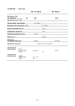
Page 21: ...ectable by DIP switches on phono module Ausg nge Outputs PHONES 50 PRE 1 Cinch 1 Veff nom 9 Veff max 22 PRE 2 XLR Option P 1230 R 1 45 Vnom 19 6 Veff max 22 TAPE 1 TAPE 2 250 mV 100 Frequenzgang Freq...

Page 22: ...nse 0 3 dB 1 Hz 400 kHz Anstiegsgeschwindigkeit slew rate 60 V s D mpfungsfaktor damping factor 500 Ger uschspannungsabstand S N ratio 110 dB Klirrfaktor THD 0 002 Netzteilsiebung Pwr supply smoothing...

Page 23: ...em tuning system Quartz PLL digital Selektivit t selectivity f 300 kHz Narrow 80 dB Wide 60 dB Frequenzgang frequency response 1 5 dB 5 Hz 15 kHz Ger uschspannungsabstand S N ratio IEC MONO 79 dB STER...

Page 24: ...lled on the PCB Values for the emitter resistors R746 747 and R846 847 are 0 22 Ohms List of circuit and assembly diagrams Sonderbauteile Special parts Bedienteil Front panel board P1230R PA1230R Circ...

Page 25: ......

Page 26: ......

Page 27: ......

Page 28: ......

Page 29: ......

Page 30: ......

Page 31: ......

Page 32: ......

Page 33: ......

Page 34: ......

Page 35: ......

Page 36: ......

Page 37: ......

Page 38: ......

Page 39: ......

Page 40: ......

Page 41: ......

Page 42: ......

Page 43: ......

Page 44: ......

Page 45: ......

Page 46: ......

Page 47: ......

Page 48: ......

Page 49: ......

Page 50: ......

Page 51: ......

Page 52: ......

Page 53: ......

Page 54: ......

Page 55: ......

Page 56: ......

Page 57: ......

Page 58: ......

Reviews: