


3
INSTALLATION
FLUSH PANEL MOUNTING
1.
Select location which is reasonably clean and dry, with adequate
access. Ambient limits 0 to 40°C.
2.
Remove fascia cover (Fig.4) using the key supplied (Fig.2).
3.
Rotate locking screws through a quarter turn and separate
controller sections (Fig.5).
4.
Unplug ribbon cable by pressing outwards the side locking wings
(Fig.6). (If flush mounted, omit steps 5 to 8 and proceed to 9).
WALL MOUNTING (or Rear Panel Mounting)
5.
Remove conduit cut-outs as required with a sharp knife. Screw
back section to wall (Fig.7). When trunking is used the controller
must be mounted using 32mm spacer bushes.
6.
Connect wiring in accordance with appropriate scheme diagram.
Observe wiring precautions given in table on Page 8.
7.
Move slide switch 'S' to correct position for the application (see
Commissioning, Fig.16).
8.
Reassemble controller by plugging ribbon cable back into socket
on rear power board. Take care to align plug and socket the right
way round - DO NOT FORCE. Push controller case onto base
section, locating the two guide rods into the bushes and turn
screws to relock (Fig.8).
FLUSH PANEL MOUNTING
9.
Move slide switch 'S' to correct position for the application (see
Commissioning, Fig.16).
10. Remove power board from the base section by undoing two front
screws 'A' (discard) and two rear screws 'B' which mount the
bushes (Fig.9).
11. Refit the two bushes into base section with screws 'B' (Fig.10).
12. Place the two hexagonal space bushes 'C' (supplied) over the
locking rods in front part of controller (Fig.11).
13. Carefully fold the ribbon cable as shown (Fig.12). Reposition the
power board over the ribbon cable (board points to rear when
assembled) using the two screws/washers 'D' supplied (Fig.13).
14. Fit controller into panel cut-out (138 x 138mm) and secure using
brackets/screws provided (Fig.14).
15. Wire up as step 6 and remove conduit cut-outs from base section,
see step 5.
16. Plug ribbon cable back into socket. Observe right way round - DO
NOT FORCE. Refit back of controller, locating the two bushes on
the guide rods and turn screws to relock (Fig.15).
Caution
Do not switch on mains power until commissioning checks 1 to 8
have been carried out.
COMMISSIONING
SYSTEM CHECK
1.
Check that all equipment is correctly located and fitted.
2.
Remove controller from back section (see Installation 2, 3 and 4).
3.
Check all control circuit wiring.
a.
Ensure there is no mains on low voltage (upper) terminals.
b.
Check all wires are in accordance with scheme diagram or
diagrams on this leaflet.
c.
Ensure all necessary links and resistors have been connected
or removed as instructed.
4.
Check slide switch 'S' is in correct position for application.
5.
Temporarily remove sensor wires and substitute a simulator. If not
available, connect a variable resistor, or switchable fixed resistors
of values approximately 2200 Ohms, 1800 Ohms and 1500 Ohms.
6.
Rotate D.P.H. selector switch to fast run position 'T'.
7.
Reassemble case, plugging in (ribbon cable) if unplugged.
8.
Set Td to 20°C, Tn to 10°C, and override switch to Auto
. If a
simulator is used, set this to 16°C. Otherwise select the 1800 Ohm
resistance to simulate this value.
9.
Switch on power supply and set the clock as detailed in 'SETTING
THE CLOCK'.
10. Override time switch ON then OFF. See dialogue or digital clock
setting instructions for details.
11. Plant and R2 relays should now be 'Off'. (Neither LED illuminated).
12. Override time switch 'On'. After approximately 15 seconds the
'Plant' relay should energise and after a further 15 seconds relay
R2, when slide switch 'S' is in position 'A'. (Both LEDs illuminated).
13. This test simulates a 'Fast Run' optimum start period of 2 hours
speeded up to 30 seconds with a plant switch-on half way through
this period because the simulated inside temperature of 16°C is
half way between 12°C (max. preheat) and 20°C (zero preheat).
Boost is terminated when the relay R2 is energised at the end of
this period.
14. Override time switch to 'Off' position. Both plant and R2 relays
should de-energise. (Both LEDs off).
15. Set simulator above 20°C or select the 1500 Ohms resistance.
Relay R2 should energise (
LED illuminated).
16. Set simulator below 10°C or select the 2200 Ohm resistance. The
'Plant' relay should energise (
LED illuminated). This test is to
check frost protection.
17. Switch off power supply. Open case. Remove simulator or
resistances. Reconnect room sensor wires. Reassemble case.
Switch on power supply.
18. Set time switch and parameters as following section.
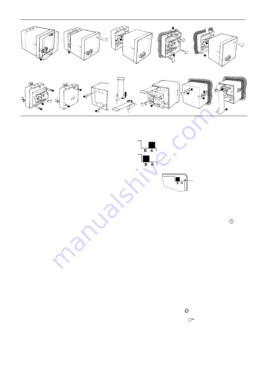
WALL MOUNTING
Fig.4
Fig.5
Fig.6
Fig.7
Fig.8
Fig.9
Fig.10
Fig.11
Fig.12
Fig.13
Fig.14
Fig.15
Position 'A' gives termination of boost on relay R2,
for use on applications involving day control from a
compensator or other Satchwell controllers (see
connection diagrams Fig.4 and Fig.5).
Position 'B' gives a single pole change-over output
from relay R2 for day control of pump/boiler and/or
motorised valve (see connection diagrams Fig.6,
Fig.7 and Fig.8).
Slide
switch 'S'
Fig.16
Slide switch 'S' on circuit
board inside front portion
of controller


