background image

Alternative 2: In-rail charging (Accessory for article number 50100059)

If the in-rail charging option is chosen, the lift unit must be fitted with a charger contact (70200062) and charger rails 
before installation. The charger that is included with the lift unit is used. 


Alteration of the charging method must be performed by authorized  


personnel according to instructions issued by Handicare AB. 

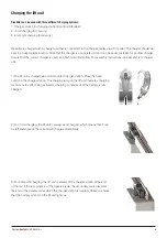
1) Set the charging points for in-rail charging. To set the charging points for in-rail charging, remove the spring pins that 
hold the charger plate in place. Then, the dip switch on the circuit board is set for the desired charging function.

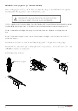
2) Check to ensure that the charger plate springs in and out when pressure is applied to the charger plate, see 
fig 2.

3) Check to ensure that charger rails have been installed (installation of charger rails is described in the installation 
manual for MilkyWay).

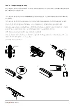
4) Guide the lift unit onto the rail so that the plus on the charging point is on the right side, according to fig 3.

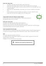
5) Connect the red cable to the charger rail on the right side, the charger plate’s plus side (positive), and the black cable 
on the left side (negative), according to fig 4.

6) Install the end-stop on the rail.

1

2

3

+

4

+ Plus

NOTE! No spring pin

6

M A N U A L System

RoMedic

TM

Summary of Contents for RiseAtlas625M

Page 1: ...ted with a quick release trolley which readily allows for dismantling of the ceiling lift unit from the rail Visual inspection Inspect lift functions regularly Check to ensure that product is free fro...

Page 2: ...ection 10 Using the product 11 16 Important information 11 Before use 11 Safe working load 12 Description of functions and symbols 13 Hand control 13 Information panel 14 Preventive service maintenanc...

Page 3: ...for at least 3 hours before it is used for the first time The lift unit is shipped with the fuse removed Prior to installation the cover is removed and a 20A fuse is inserted The fuse is packed in a b...

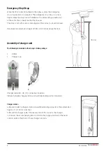
Page 4: ...cm 70 inches above the floor Assembly of charger unit The following is included in the charger station package Holder Charger cup Charger cable EU UK US connectors included fixtures between charger s...

Page 5: ...charger unit 1 The lift unit is charged via a wall mounted charger station Place the hand control in the charger station The charging lamp on the lift unit indicates charging for 15 minutes after bei...

Page 6: ...late in place Then the dip switch on the circuit board is set for the desired charging function 2 Check to ensure that the charger plate springs in and out when pressure is applied to the charger plat...

Page 7: ...2 3 Guide the lift unit onto the rail so that the plus on the charging point is on the right side according to fig 3 4 Mount charger contacts according to figure 4 NOTE Push the charger contact A in a...

Page 8: ...minutes Battery status in rail charging The battery symbol lights green when battery capacity exceeds 50 When the lift unit is activated the battery symbol lights green for 15 minutes If the battery...

Page 9: ...te the lift unit 90 degrees to lock the T fitting in the lift unit 4 Click the locking clip into place 5 Check to ensure that the lift unit is secured to the trolley and that it can be moved along the...

Page 10: ...on by lifting a person not a user using an approved lifting sling At the same time check both the user manual and electrical emergency lowering function with someone in the lift See section on Emergen...

Page 11: ...unattended in a lifting situation Warranty does only apply if repairs or alterations are made to the lift by personnel who are authorized RiseAtlas must not come in direct contact with water RiseAtla...

Page 12: ...ive accessory Below is a brief description of the functions that are available for caregivers and users Symbols on the product Battery status Emergency stop The lift requires service or maintenance Di...

Page 13: ...done the battery symbol on the lift unit s information display is lit for 2 seconds showing the current battery status If the battery symbol does not light and the lift unit is not activated check tha...

Page 14: ...heavy Read user manual Often the book symbol will light up at the same time as another symbol lights up indicating that the user should read the user manual before using the lift again Night light Ris...

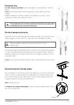
Page 15: ...upplied Allen key in the hole as indicated fig 4 Turn it counter clockwise to lower and clockwise to raise the sling bar Always ensure that emergency lowering is done in an appropriate location NOTE L...

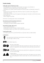
Page 16: ...l If the lift cannot be run down check to ensure that load is applied to the lift strap that the battery symbol does not indicate low battery charge level that the directional indicators on the button...

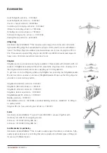
Page 17: ...lingBar two point sling bar SlingBarSpreader M side bars can be used as an accessory SlingBarSpreader M open up the lifting sling and provide for a more reclined position SlingBar XS 250 mm article no...

Page 18: ...ntaining phenol or chlorine as this could damage the aluminium and the plastic materials If disinfection is needed 70 ethanol 45 isopropanol or similar should be used Storage and transportation If the...

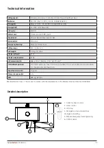
Page 19: ...ax 0 9A Lift motor 24VDC Motor cover Flame resistant ABS plastic Sound level Unload 55 dB Max load 57 dB Hand control Electronic Emergency lowering Manual and electrical Lifting range 240 cm 95 inch L...

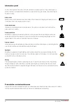
Page 20: ...vironment and quality of care and at the same time achieves significant cost savings Always make sure that you have the correct version of the manual The most recent version of all manuals are availab...

Reviews: