background image

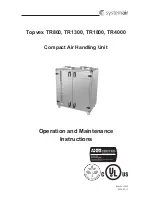
Topvex TR800, TR1300, TR1800, TR4000

Operation and Maintenance Instructions

Systemair Inc.

3

2.2 Description of Internal Components

2.2.1 Supply and Extract Air Fans

The fans have external rotor motors of EC type which can be steplessly controlled individually 0 - 100%. It 

is possible to program the speed in 2 steps (normal/reduced) depending on the programming of the week 

schedule. The motor bearings are permanently lubricated and maintenance free. It is possible to remove the 

fans for cleaning. (Chapter 5)

2.2.1.1 Pressure Transmitter and clogged filter alarm

Two pressure transmitters maintain the airflow at a constant level (CAV) by measuring the differential pressure 

over the inlet cone of the fan impellers. The pressure transmitters are installed from factory in all units. An 

accessory kit is available to convert the unit to a VAV in order to maintain a constant pressure in the duct. See 

“VAV Installation Instructions” manual (420300) for more information.

In addition, the pressure transmitters measures the differential pressure over the supply and extract air filters.

When the pressure drop reaches the set value an alarm is triggered in the main controller. The differential 

pressure can be set between 0.2 in.wg. (40Pa) and 1.2 in.wg. (300 Pa). The pressure switch is preset from 

factory to 1.0 in.wg. (240 Pa).

2.2.2 Outdoor and Extract Air Filters and Pre-Filter**

The filters are of bag filter type with filter quality MERV13 for the outdoor air filter and MERV9 for the extract 

air filter. The filters need to be replaced when dirty. New sets of filters can be acquired from your installer or 

wholesaler. 

The pre-filter(s) is of a screen type  and can be cleaned by using soap water or compressed air. It can be  

acquired from installer or wholesaler.

2.2.3 Heat Exchanger

Topvex TR models are equipped with a highly efficient, belt driven, rotating heat exchanger. Required supply 

air temperature is therefore normally maintained without adding additional heat. The operation of the heat 

exchanger is automatic and depends on the set temperature. An extra driving belt is included on the rotor on 

delivery (pos.6 figure 1).

The heat exchanger is removable for cleaning and maintenance. (Chapter 5)

2.2.3.1 Rotor Motor

The rotor motor drives the exchanger rotor with a constant rotational speed as long as there is a heat demand. 

The motor is controlled by an on/off digital control signal (pos.5 figure 1).

2.2.3.2 Rotation Sensor

A sensor registers the rotation of the heat exchanger rotor. It’s connected to the main controller which gives 

an alarm if the rotor stops while there is a heat demand (pos.7 figure 1).

**(only with units with pre-heater)

Summary of Contents for Topvex TR1300

Page 1: ...Topvex TR800 TR1300 TR1800 TR4000 Compact Air Handling Unit Operation and Maintenance Instructions Item 415005 2022 05 13...

Page 2: ...ing the Control Panel 8 4 Commissioning 9 4 1 Before Starting the System 9 4 2 Initial Setup of the Unit 9 4 3 Menu Overview Operator Service Level 12 4 4 Free Cooling Description 23 4 5 Cooling Recov...

Page 3: ...er Make sure that the Mains supply to the unit is disconnected before performing any maintenance or electrical work All electrical connections must be carried out in accordance with local rules and re...

Page 4: ...ir D Connection exhaust air 1 Fan supply air 2 Fan extract air 3 Filter extract air 4 Filter outdoor air 5 Heat exchanger 6 Rotor motor 7 Rotor belt 8 Re heater electric or hydronic 9 Pre heater elect...

Page 5: ...wg 40Pa and 1 2 in wg 300 Pa The pressure switch is preset from factory to 1 0 in wg 240 Pa 2 2 2 Outdoor and Extract Air Filters and Pre Filter The filters are of bag filter type with filter quality...

Page 6: ...t See HWC EPH Installation Instructions manual 420353 for correct procedure In Topvex FR800 3800 all temperature sensors are mounted and wired inside the unit except for the supply air sensor which is...

Page 7: ...For pre heater components please refer to the Pre Heater installation instructions 420353 Fig 3 Electrical components Topvex TR800 1800 EL Position Description 1 Controller E 28 UC 2 Transformer 208...

Page 8: ...ormer 208 230 24VAC TR24 3 Terminals for internal and external components TB3 4 Terminals for internal wiring TB2 5 Terminals for main power voltage to the unit TB1 6 Contactor K1 On Off rotor motor 7...

Page 9: ...TR4000 Position Description 1 Controller E 28 UC 2 Transformer 208 230 24VAC TR24 3 Terminals for internal and external components TB3 4 Terminals for internal wiring TB2 5 Terminals for main power v...

Page 10: ...D Indicates alarm by flashing red light 3 Write LED Indicates by flashing yellow light that parameters can be set or changed 4 OK button Press this button to be able to change or set parameters whenev...

Page 11: ...stallation instructions The unit is correctly wired Sound attenuators if used are installed and that the duct system is correctly connected to the unit Outdoor air intake is positioned with sufficient...

Page 12: ...HT to select next digit Press OK to confirm and enter Per 2 START time Change time using the UP DOWN arrow buttons Press RIGHT to select next digit Press OK to confirm and enter Per 2 STOP time Change...

Page 13: ...ext digit Press OK to confirm and enter Per 2 START time Change time using the UP DOWN arrow buttons Press RIGHT to select next digit Press OK to confirm and enter Per 2 STOP time Change time using th...

Page 14: ...to the Service level in the table below are marked with grey background color To logon to the Service level use code 2222 under Access rights Main menu item Sub menu item 1 Sub menu item 2 Explanation...

Page 15: ...of the cooling recovery function External set point Not active Shows the status of the external set point Alarm events Shows all registered alarms along with the time and date they occurred Move down...

Page 16: ...perature in the water heating coil Only visible for HW units Exhaust air temp Actual F Shows the actual exhaust air temperature Efficiency Exchanger Actual Shows the actual heat recovery efficiency Th...

Page 17: ...figured for Flow control Flow control EAF Setp 1 1 647 4 CFM Setp 1 2 323 7 CFM Set the normal 1 1 and reduced 1 2 airflow for the extract air fan Outdoor comp Setp 1 4 F 5 9 CFM 32 F 0 CFM Act Comp 0...

Page 18: ...ternal pressure set point for normal speed 1 1 and reduced speed 1 2 for the supply air fan Outdoor comp Setp 1 4 F 0 in wg 50 F 0 in wg Act Comp 0 in wg Set the EAF pressure compensation for the sett...

Page 19: ...number of consecutive days from one and upwards The dates are in the format MM DD When the current date falls within a holiday period the scheduler will use the settings for the weekday Holiday Manua...

Page 20: ...put 0 100 Cooling Auto Manual set 0 0 Set the cooling to Auto Manual or Off Set the manual output 0 100 Note Needs to be activated in order to be visible here P1 Heating Auto P1 Exchanger Auto Set the...

Page 21: ...Set P band and I time for the Shutdown function Note See Corrigo E ventilation manual for deeper explanation Frost protection Active Setp shutdown 77 0 F P band active 41 0 F P band active 41 F means...

Page 22: ...ser settings they were saved as earlier Select Yes or No Save user settings No The current configuration can be saved in a separate memory area and can later be restored using the previous menu Restor...

Page 23: ...t the delay in minutes from the time when the free cooling sequence has stopped until a possible heating sequence is initiated i e how long a cooler room temperature than set temperature can be accept...

Page 24: ...limit 5 Set the humidity control to Humid Dehumidification Dehumidification Humidification or Not active Set the start limit and stop limit in RH Applicable for external Humidification or Dehumidific...

Page 25: ...tart and stop temperature intervals Stop conditions Outdoor temp above the set max value 64 4 F 18 C or below the set min value condensation risk 50 F 10 C The room temp extract air temp is below the...

Page 26: ...ir for a defined period of time preventing any frost build up before going back to normal ventilation mode Recirculation There are 3 different recirculation configurations First is a 5th port configur...

Page 27: ...at a proper lifting device is used Use protective clothing Caution If the unit is installed in a cold place make sure that all joints are covered with insulation and tape well Duct connections duct en...

Page 28: ...be ordered from Systemair Operation time between filter changes depends on the air pollution at the installation site A differential pressure switch indicates when it s time to change the filters This...

Page 29: ...g 8 Removing the fans Fig 7 Removing the heat exchanger Note Make sure that the rotor motor is not exposed to moisture After extended use dust may build up in the exchanger and block the air flow It i...

Page 30: ...rs dust may have deposited on the surface of the coil This may reduce coil capacity The coil can be cleaned with a pressure washer with misting jets or with compressed air Cleaning should be carried o...

Page 31: ...torques at the edge of the cover using a small screwdriver and at the same time pulling the edges outwards 2 Grip the battery firmly with your fingers and lift it upwards until it rises from its holde...

Page 32: ...ting in control panel schedules auto manual operation airflow set points etc 2 Wheel motor does not start Check if there are any alarm messages Check if the automatic fuse AS1 is tripped figure 3 pos...

Page 33: ...31 6 Service Before calling your service representative make a note of the specification and production number from the type label figure 9 Fig 9 Type label Position Description 1 Model number 2 Item...

Page 34: ...Topvex TR800 TR1300 TR1800 TR4000 Operation and Maintenance Instructions Systemair Inc 32 Notes...

Page 35: ...Topvex TR800 TR1300 TR1800 TR4000 Operation and Maintenance Instructions Systemair Inc 33 Notes...

Page 36: ...improvements to the contents of this manual without prior notice Systemair Inc 50 Kanalflakt Way Bouctouche NB E4S3M5 Canada Phone 1 800 263 7081 10048 Industrial Blvd KS 66215 United States Phone 1...

Reviews: