


5
installation manual
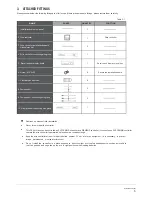
5. MATERIAL AND SIZE OF THE PIPING
Size(mm)
Pipe Material
Copper Pipe for Air Conditioner
Model
Φ
8
Φ
8
AHU
5HP
(Liquid in)
(Liquid out)
Φ
12.7
Φ
12.7
AHU
10HP
Table.5-1
6. REFRIGERANT PIPE
CAUTION
AHU
20HP
Φ
16
Φ
16
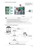
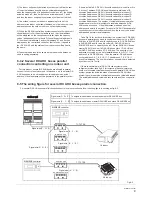
The connecting distance of each control box and indoor unit
should not more than 8 m.
This control box can only connect to R410A refrigerant system.
This control box can only connect to VRF system.
This control box can not connect heat recovery system.
During the installation of connecting pipes, do not let air, dust, or
other sundries enter to the piping system.
Install the connecting pipe only after the indoor and outdoor
units have been fixed.
When installing the connecting pipes, it must be kept dry and do
not let water enter to the piping system.
The connecting copper pipes must be wrapped with thermal
insulation materials (usually the thickness should be more than
10mm; in some humid area it should be thicken properly).
1
2
3
4
5
6
7
8
Table.6-1
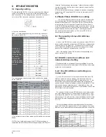
L
1,
L
2
a
1,
a
2,
b
1,
b
2,
c
1,
c
2
A, B
Pipe name
Code(refer to Fig.6-1)
Controller box main pipe
Controller box aux. pipe
Controller box branch joint assembly
e.x.1: Refer to
Fig.6-1 ,
the capacity of downstream controller box to L4
is 560+280+140=980, the pipe is
Φ
19.1.
6-1 Pipe classification
Capacity of
controller box
A(×100W)
Size of main pipe(mm)
Liquid side(mm)
Φ
12.7
Φ
15.9
Φ
19.1
Φ
22.2
200<A<460
460
≤
A<660
660
≤
A<1350
1350
≤
A
Table.6-2
JOINT
02
JOINT
01
JOINT
03
JOINT
04
Available branch joint
6-3 Example
Controller box capacity
A(×100W)
Φ
9.5
Φ
12.7
Φ
15.9
Table.6-3
Take (56+36+20) kW that composed by three controller
box as an example to clarify the pipe selection.
The branch pipe at the controller box.
There are a~c branch pipe at the controller box, the branch
pipe diameter should be select as Table. 6-3.
Main pipe at the controller box (Refer to Table. 6-2)
The main pipe L
1
L
2
with
N
1
, N
2
downstream controller box that
total capacity is 280+140=420, the pipe L
1
diameter is
Φ
12.7,
thus select
JOINT 01
for the branch joint B.
The branch joint A with N
0
~N
2
downstream controller box that
total capacity is 560+280+140=980, thus select
JOINT 0
3 for
the branch joint A.
A
B
1)
2)
AHU
5HP
90<A
≤
200
Liquld side(mm)
AHU
10HP
200<A
≤
360
AHU
20HP
360<A
≤
560
Fig.6-1
6-2 Size of joint pipe for 410A indoor unit
NOTE
a2+L4
≤
8m b2+L2+L4
≤
8m c2+L2+L4
≤
8m
A
a
1
L
1
B
b
1
c
1
Liquid pipe
Gas pipe
Indoor unit
outdoor unit
a
2
b
2
c
2
L
2
Liquid pipe
AHUKZ-03B(56kW)
AHUKZ-02B(28W)
AHUKZ-01B(14kW)
A
B
N
0
N
1
N
2
L
3
L
4
The connecting distance of each control box and indoor unit
should not more than 8 m
Summary of Contents for SYSVRF AHU 10HP S
Page 2: ......
Page 16: ...MD14IU 033BW 202000172668 ...


